How to Use Flip Microcontroller: Examples, Pinouts, and Specs
Introduction
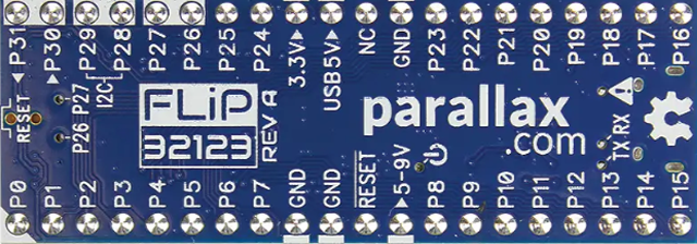
The Flip Microcontroller (Manufacturer Part ID: 32123) by Parallax is a compact and versatile microcontroller designed for low-power applications. It features built-in memory, multiple I/O capabilities, and is ideal for use in embedded systems and Internet of Things (IoT) projects. Its small form factor and efficient design make it a popular choice for developers looking to create compact, energy-efficient devices.
Explore Projects Built with Flip Microcontroller


Explore Projects Built with Flip Microcontroller
Common Applications and Use Cases
- IoT devices and smart home systems
- Wearable technology
- Robotics and automation
- Data logging and environmental monitoring
- Educational projects and prototyping
Technical Specifications
The Flip Microcontroller is engineered to deliver reliable performance in a variety of applications. Below are its key technical specifications:
| Specification | Details |
|---|---|
| Manufacturer | Parallax |
| Part ID | 32123 |
| Operating Voltage | 3.3V to 5V |
| Power Consumption | Low-power design (<50 mA typical) |
| Clock Speed | 80 MHz |
| Flash Memory | 512 KB |
| RAM | 64 KB |
| GPIO Pins | 20 (configurable as digital/analog) |
| Communication Interfaces | UART, I2C, SPI |
| Dimensions | 1.5" x 0.7" (38mm x 18mm) |
| Operating Temperature Range | -40°C to 85°C |
Pin Configuration and Descriptions
The Flip Microcontroller features a total of 20 General Purpose Input/Output (GPIO) pins, along with power and communication pins. Below is the pinout description:
| Pin Number | Label | Function |
|---|---|---|
| 1 | GND | Ground |
| 2 | 3.3V | 3.3V Power Output |
| 3 | 5V | 5V Power Output |
| 4-13 | GPIO0-9 | General Purpose I/O (Digital/Analog) |
| 14 | TX | UART Transmit |
| 15 | RX | UART Receive |
| 16 | SCL | I2C Clock |
| 17 | SDA | I2C Data |
| 18 | MOSI | SPI Master Out Slave In |
| 19 | MISO | SPI Master In Slave Out |
| 20 | SCK | SPI Clock |
Usage Instructions
The Flip Microcontroller is easy to integrate into a variety of projects. Follow the steps below to use it effectively:
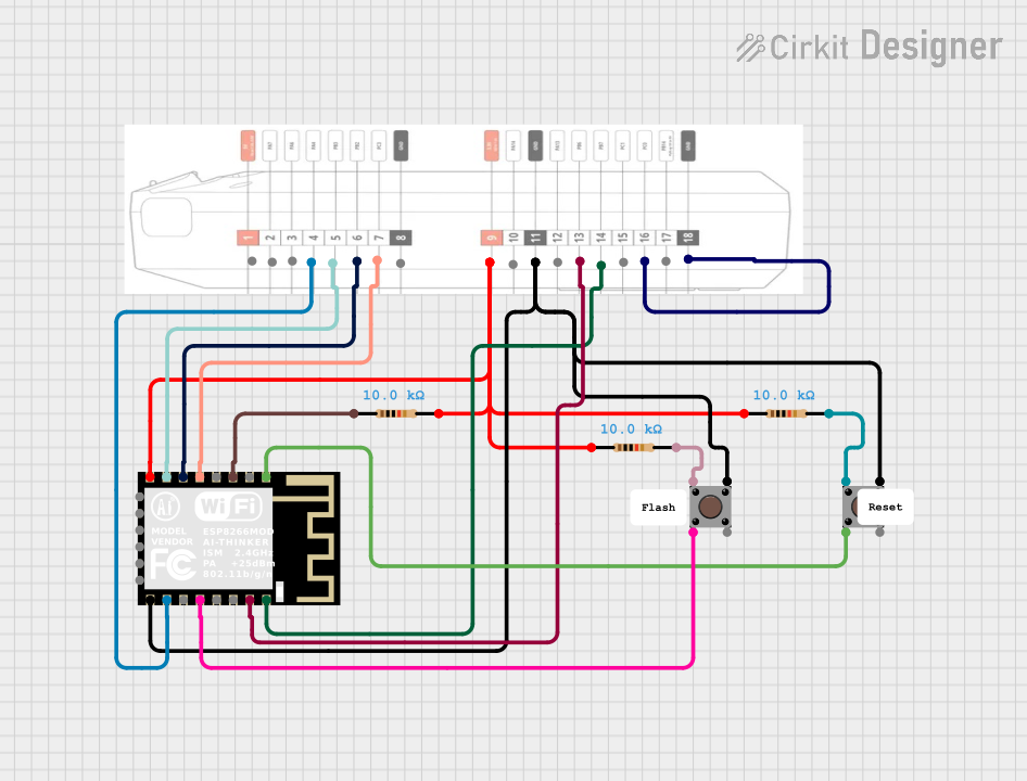
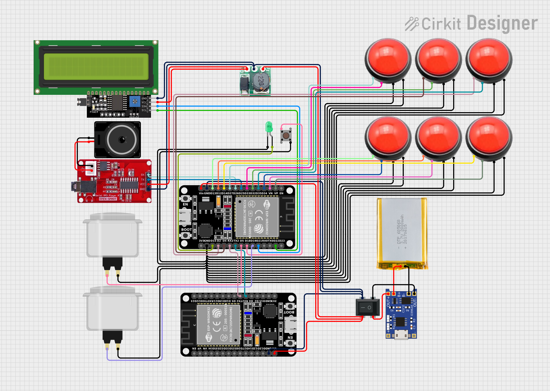
How to Use the Flip Microcontroller in a Circuit
Powering the Microcontroller:
- Connect the GND pin to the ground of your power source.
- Supply 3.3V or 5V to the respective power input pins. Ensure the voltage matches the operating range.
Connecting GPIO Pins:
- Use GPIO pins for digital or analog input/output. Configure them in your code as needed.
- For analog input, ensure the input voltage does not exceed the operating voltage.
Communication Interfaces:
- Use the UART pins (TX and RX) for serial communication.
- For I2C communication, connect the SCL and SDA pins to the corresponding pins on your peripheral device.
- For SPI communication, connect MOSI, MISO, and SCK to the respective pins on your SPI device.
Programming the Microcontroller:
- The Flip Microcontroller can be programmed using the Parallax IDE or other compatible software.
- Connect the microcontroller to your computer via a USB-to-serial adapter for programming.
Important Considerations and Best Practices
- Voltage Levels: Ensure all connected devices operate within the same voltage range (3.3V or 5V).
- Pin Protection: Avoid exceeding the maximum current rating of GPIO pins (20 mA per pin). Use resistors or buffers if necessary.
- Decoupling Capacitors: Place decoupling capacitors (e.g., 0.1 µF) near the power pins to reduce noise.
- Code Optimization: Optimize your code to minimize power consumption, especially for battery-powered applications.
Example: Connecting to an Arduino UNO
The Flip Microcontroller can be used as a peripheral device with an Arduino UNO. Below is an example of using UART communication to send data between the two devices:
// Arduino UNO Code: Communicating with Flip Microcontroller via UART

void setup() {
  Serial.begin(9600); // Initialize UART communication at 9600 baud
  delay(1000);        // Wait for Flip Microcontroller to initialize
}

void loop() {
  Serial.println("Hello, Flip Microcontroller!"); // Send data to Flip
  delay(1000); // Wait 1 second before sending the next message
}
Troubleshooting and FAQs
Common Issues and Solutions
Microcontroller Not Powering On
- Cause: Incorrect power supply voltage or loose connections.
- Solution: Verify the power supply voltage (3.3V or 5V) and ensure all connections are secure.
GPIO Pins Not Responding
- Cause: Incorrect pin configuration in the code.
- Solution: Double-check your code to ensure the pins are configured as input or output as required.
Communication Issues (UART/I2C/SPI)
- Cause: Mismatched baud rate, incorrect wiring, or incompatible devices.
- Solution: Verify the communication settings (e.g., baud rate for UART) and check the wiring.
Overheating
- Cause: Excessive current draw or short circuits.
- Solution: Ensure the current draw does not exceed the microcontroller's limits. Check for short circuits.
FAQs
Q1: Can the Flip Microcontroller operate at 5V?
A1: Yes, the Flip Microcontroller supports both 3.3V and 5V operation. Ensure all connected devices are compatible with the chosen voltage.
Q2: How do I reset the microcontroller?
A2: The Flip Microcontroller has a built-in reset pin. Momentarily connect the reset pin to ground to reset the device.
Q3: Can I use the Flip Microcontroller for battery-powered projects?
A3: Yes, its low-power design makes it suitable for battery-powered applications. Use sleep modes in your code to conserve power.
Q4: What programming languages are supported?
A4: The Flip Microcontroller can be programmed using C, C++, or Parallax's proprietary language, depending on the IDE used.
By following this documentation, you can effectively integrate the Flip Microcontroller into your projects and troubleshoot common issues with ease.