Cirkit Designer Logo
Cirkit Designer
Your all-in-one circuit design IDE
Home / 
Component Documentation

How to Use Atlas Scientific Analog Isolator: Examples, Pinouts, and Specs

Image of Atlas Scientific Analog Isolator
Cirkit Designer LogoDesign with Atlas Scientific Analog Isolator in Cirkit Designer

Introduction

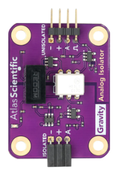
The Atlas Scientific Analog Isolator (SRV-ISO) is an essential component designed to provide electrical isolation between a sensor and the host circuit. This isolation helps to prevent signal distortion and ensures accurate and reliable data transmission, which is crucial in sensitive electronic measurements. Common applications include water quality monitoring, laboratory equipment, and any system where sensor data integrity is paramount.

Explore Projects Built with Atlas Scientific Analog Isolator

Use Cirkit Designer to design, explore, and prototype these projects online. Some projects support real-time simulation. Click "Open Project" to start designing instantly!
Battery-Powered Load Cell Amplifier with INA125 and LM324
Image of Test: A project utilizing Atlas Scientific Analog Isolator in a practical application
This circuit is a load cell signal conditioning and amplification system. It uses an INA125 instrumentation amplifier to amplify the differential signal from a load cell, with additional filtering and gain control provided by potentiometers and capacitors. The amplified signal is then monitored by a digital voltmeter, and the entire system is powered by a 12V battery with a step-up boost converter to provide stable voltage.
Cirkit Designer LogoOpen Project in Cirkit Designer
Multi-Channel Load Cell Measurement System with JYS60 Amplifiers and DAQ Integration
Image of Load Cell Circuit: A project utilizing Atlas Scientific Analog Isolator in a practical application
This is a multi-channel load cell measurement system with several JYS60 amplifiers connected to load cells for weight or force sensing. The amplified signals are directed to a DAQ system for data capture, and power is supplied through a barrel jack. Grounding is achieved via an AdaGator Side Black component.
Cirkit Designer LogoOpen Project in Cirkit Designer
ADXL335 Accelerometer Data Visualization with Oscilloscope
Image of SYS Circuit: A project utilizing Atlas Scientific Analog Isolator in a practical application
This circuit connects an AITrip ADXL335 GY-61 accelerometer to an oscilloscope for signal visualization and a 3xAA battery pack for power. The accelerometer's Z-axis output is directly monitored on the oscilloscope, allowing for real-time observation of acceleration changes along that axis. The circuit is likely used for educational or testing purposes to demonstrate how the accelerometer responds to motion.
Cirkit Designer LogoOpen Project in Cirkit Designer
Arduino Nano-Based GPS and GSM Tracking System with Load Cell Integration
Image of load cell: A project utilizing Atlas Scientific Analog Isolator in a practical application
This is a multi-functional circuit designed for location tracking, cellular communication, and weight measurement. It uses an Arduino Nano to interface with a GPS module, a GSM module, and a load cell with an HX711 amplifier, displaying data on an I2C LCD screen. Power is supplied by a Li-Ion battery through a buck converter, with a rocker switch for power control and a pushbutton for user input.
Cirkit Designer LogoOpen Project in Cirkit Designer

Explore Projects Built with Atlas Scientific Analog Isolator

Use Cirkit Designer to design, explore, and prototype these projects online. Some projects support real-time simulation. Click "Open Project" to start designing instantly!
Image of Test: A project utilizing Atlas Scientific Analog Isolator in a practical application
Battery-Powered Load Cell Amplifier with INA125 and LM324
This circuit is a load cell signal conditioning and amplification system. It uses an INA125 instrumentation amplifier to amplify the differential signal from a load cell, with additional filtering and gain control provided by potentiometers and capacitors. The amplified signal is then monitored by a digital voltmeter, and the entire system is powered by a 12V battery with a step-up boost converter to provide stable voltage.
Cirkit Designer LogoOpen Project in Cirkit Designer
Image of Load Cell Circuit: A project utilizing Atlas Scientific Analog Isolator in a practical application
Multi-Channel Load Cell Measurement System with JYS60 Amplifiers and DAQ Integration
This is a multi-channel load cell measurement system with several JYS60 amplifiers connected to load cells for weight or force sensing. The amplified signals are directed to a DAQ system for data capture, and power is supplied through a barrel jack. Grounding is achieved via an AdaGator Side Black component.
Cirkit Designer LogoOpen Project in Cirkit Designer
Image of SYS Circuit: A project utilizing Atlas Scientific Analog Isolator in a practical application
ADXL335 Accelerometer Data Visualization with Oscilloscope
This circuit connects an AITrip ADXL335 GY-61 accelerometer to an oscilloscope for signal visualization and a 3xAA battery pack for power. The accelerometer's Z-axis output is directly monitored on the oscilloscope, allowing for real-time observation of acceleration changes along that axis. The circuit is likely used for educational or testing purposes to demonstrate how the accelerometer responds to motion.
Cirkit Designer LogoOpen Project in Cirkit Designer
Image of load cell: A project utilizing Atlas Scientific Analog Isolator in a practical application
Arduino Nano-Based GPS and GSM Tracking System with Load Cell Integration
This is a multi-functional circuit designed for location tracking, cellular communication, and weight measurement. It uses an Arduino Nano to interface with a GPS module, a GSM module, and a load cell with an HX711 amplifier, displaying data on an I2C LCD screen. Power is supplied by a Li-Ion battery through a buck converter, with a rocker switch for power control and a pushbutton for user input.
Cirkit Designer LogoOpen Project in Cirkit Designer

Technical Specifications

Key Technical Details

  • Isolation Voltage: 4kV
  • Input Voltage Range: 3.3V - 5V
  • Output Voltage Range: 3.3V - 5V
  • Current Consumption: 3mA (typical at no load)
  • Operating Temperature Range: -40°C to +85°C
  • Dimensions: 56mm x 32mm x 15mm

Pin Configuration and Descriptions

Pin Number Name Description
1 V+ Input voltage (3.3V - 5V)
2 GND Ground reference for input
3 VOUT Isolated output voltage
4 GND Ground reference for output

Usage Instructions

Integration into a Circuit

  1. Power Connections: Connect the V+ and GND pins to your power supply, ensuring it is within the 3.3V to 5V range.
  2. Sensor Connection: Connect your sensor's output to the input side of the isolator.
  3. Host Circuit Connection: Connect the VOUT and GND pins to the analog input of your host circuit, such as an Arduino UNO.

Best Practices

  • Ensure that the power supply is stable and within the specified voltage range to avoid damage.
  • Avoid running high-current carrying wires near the isolator to prevent interference.
  • Use twisted-pair wires for the input and output connections to minimize noise.

Example Code for Arduino UNO

// Analog input pin connected to the isolator output
const int analogInPin = A0; 

void setup() {
  // initialize serial communications at 9600 bps:
  Serial.begin(9600);
}

void loop() {
  // read the analog value from the isolator output
  int sensorValue = analogRead(analogInPin); 

  // Convert the analog reading (which goes from 0 - 1023) to a voltage (0 - 5V):
  float voltage = sensorValue * (5.0 / 1023.0); 

  // print the voltage to the Serial Monitor
  Serial.println(voltage); 

  // wait 2 milliseconds before the next loop
  delay(2); 
}

Troubleshooting and FAQs

Common Issues

  • No Output Voltage: Ensure that the input voltage is within the specified range and that the power supply is properly connected.
  • Inaccurate Readings: Check for any sources of electromagnetic interference near the isolator and sensor. Ensure that the sensor is functioning correctly.
  • Intermittent Signal: Verify that all connections are secure and that there are no breaks in the wiring.

FAQs

Q: Can the isolator be used with both analog and digital signals? A: The SRV-ISO is designed for analog signals. For digital signal isolation, a different type of isolator is required.

Q: Is calibration required for the isolator? A: No, the isolator does not require calibration as it does not affect the scale of the analog signal.

Q: How do I know if the isolator is functioning properly? A: You can test the isolator by measuring the output voltage while providing a known input voltage. The output should closely match the input if the isolator is working correctly.

For further assistance, please contact Atlas Scientific's technical support.