
How to Use POT: Examples, Pinouts, and Specs
 Design with POT in Cirkit Designer
Introduction
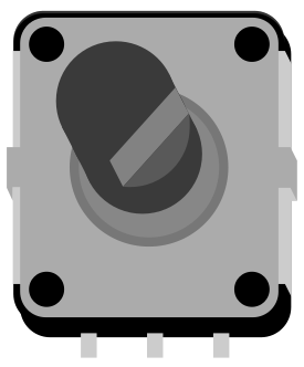
A potentiometer (commonly referred to as a POT) is a three-terminal variable resistor that allows users to adjust voltage levels in a circuit. By rotating or sliding its wiper, the resistance between its terminals changes, enabling precise control of current flow and signal levels. Potentiometers are widely used in applications such as volume controls, light dimmers, and sensor calibration.
Explore Projects Built with POT
 Open Project in Cirkit Designer
 Open Project in Cirkit Designer
 Open Project in Cirkit Designer
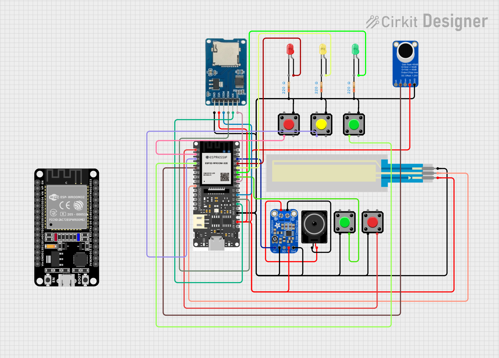 Open Project in Cirkit Designer
Explore Projects Built with POT
Open Project in Cirkit DesignerOpen Project in Cirkit DesignerOpen Project in Cirkit DesignerOpen Project in Cirkit DesignerCommon Applications:
- Audio equipment (e.g., volume and tone control)
- Light dimming circuits
- Adjustable power supplies
- Sensor calibration and tuning
- Position sensing in joysticks and servos
Technical Specifications
Below are the general technical specifications for a standard potentiometer. Note that specific values may vary depending on the model and manufacturer.
| Parameter | Specification |
|---|---|
| Resistance Range | 1 kΩ to 1 MΩ (common values: 10 kΩ) |
| Power Rating | 0.1 W to 2 W |
| Tolerance | ±10% to ±20% |
| Adjustment Type | Rotary or Linear (slider) |
| Operating Voltage | Up to 50 V DC |
| Operating Temperature | -40°C to +125°C |
Pin Configuration
A potentiometer typically has three pins:
| Pin | Description |
|---|---|
| Pin 1 | Fixed terminal 1 (connects to one end of the resistor) |
| Pin 2 | Wiper terminal (variable output voltage) |
| Pin 3 | Fixed terminal 2 (connects to the other end of the resistor) |
The wiper (Pin 2) moves along the resistive track, dividing the voltage between Pin 1 and Pin 3.
Usage Instructions
How to Use a Potentiometer in a Circuit
Basic Voltage Divider Configuration:
- Connect Pin 1 to the positive voltage supply (e.g., Vcc).
- Connect Pin 3 to ground (GND).
- Use Pin 2 (wiper) to output a variable voltage between Vcc and GND.
Adjusting Resistance:
- Use the potentiometer as a variable resistor by connecting only Pin 1 and Pin 2 (or Pin 2 and Pin 3). The resistance changes as the wiper moves.
Connecting to an Arduino UNO:
- Potentiometers are often used to provide analog input to microcontrollers like the Arduino UNO. Below is an example of how to connect and read a potentiometer's value.
Example Arduino Code
// This code reads the value of a potentiometer connected to an Arduino UNO
// and outputs the value to the Serial Monitor.

const int potPin = A0; // Connect the wiper (Pin 2) of the potentiometer to A0
int potValue = 0;      // Variable to store the potentiometer value

void setup() {
  Serial.begin(9600); // Initialize serial communication at 9600 baud
}

void loop() {
  potValue = analogRead(potPin); // Read the analog value (0-1023)
  Serial.print("Potentiometer Value: ");
  Serial.println(potValue); // Print the value to the Serial Monitor
  delay(100); // Small delay for stability
}
Important Considerations:
- Power Rating: Ensure the potentiometer's power rating is not exceeded to avoid overheating or damage.
- Mechanical Limits: Avoid forcing the potentiometer beyond its physical rotation or sliding limits.
- Noise: In some cases, potentiometers may introduce electrical noise. Use capacitors to filter noise if necessary.
Troubleshooting and FAQs
Common Issues and Solutions
Issue: The potentiometer output is unstable or noisy.
- Solution: Add a small capacitor (e.g., 0.1 µF) between the wiper and ground to filter noise.
Issue: The potentiometer does not vary the output voltage.
- Solution: Verify the connections. Ensure Pin 1 is connected to Vcc, Pin 3 to GND, and Pin 2 is used as the output.
Issue: The potentiometer feels stuck or difficult to turn.
- Solution: Check for physical damage or debris. Replace the potentiometer if necessary.
Issue: The potentiometer overheats during operation.
- Solution: Ensure the power dissipation does not exceed the rated power of the potentiometer.
FAQs
Q: Can I use a potentiometer to control motor speed?
A: Yes, but it is typically used to control the input signal to a motor driver circuit, not directly to the motor.Q: What is the difference between a linear and logarithmic potentiometer?
A: A linear potentiometer changes resistance uniformly, while a logarithmic potentiometer changes resistance exponentially, often used in audio applications.Q: Can I use a potentiometer as a position sensor?
A: Yes, potentiometers are commonly used as position sensors in applications like joysticks and servo feedback systems.
By following this documentation, you can effectively use a potentiometer in your electronic projects!