How to Use 12V limiter: Examples, Pinouts, and Specs

Introduction
The 12V limiter is an electronic component designed to restrict the output voltage to a maximum of 12 volts. It is commonly used to protect sensitive electronic circuits from overvoltage conditions, ensuring that the connected components operate within their safe voltage range. This device is particularly useful in power supply systems, automotive electronics, and battery-powered devices where voltage spikes or fluctuations may occur.
Explore Projects Built with 12V limiter

Explore Projects Built with 12V limiter
Common Applications
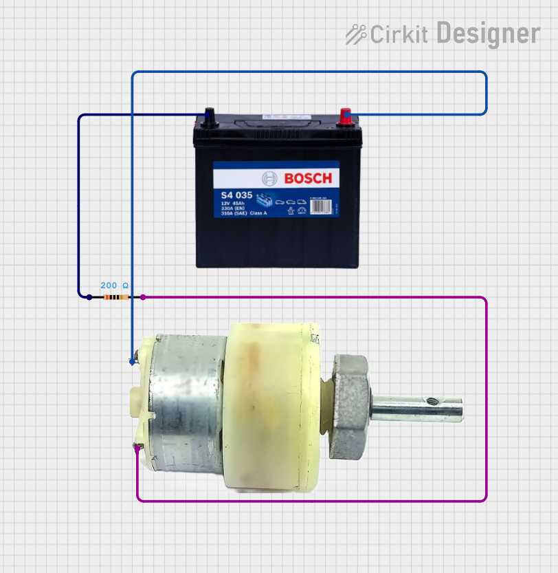
- Voltage regulation in power supply circuits
- Protection of sensitive components in automotive systems
- Battery-powered devices to prevent overvoltage damage
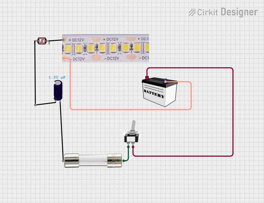
- LED lighting systems to maintain consistent brightness
- General-purpose overvoltage protection in electronic circuits
Technical Specifications
The following table outlines the key technical details of the 12V limiter:
| Parameter | Value |
|---|---|
| Maximum Input Voltage | 15V to 30V (varies by model) |
| Output Voltage | 12V ± 0.5V |
| Maximum Current | 1A to 5A (depending on the model) |
| Power Dissipation | Up to 10W |
| Operating Temperature | -40°C to +85°C |
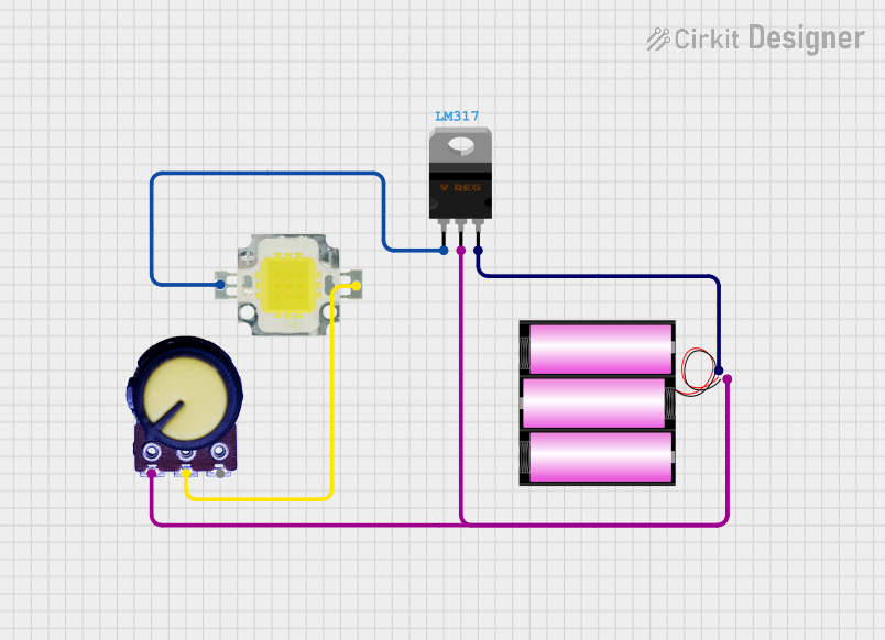
| Package Type | TO-220, SMD, or DIP |
Pin Configuration
The pin configuration of a typical 12V limiter (e.g., TO-220 package) is as follows:
| Pin Number | Pin Name | Description |
|---|---|---|
| 1 | Input | Connects to the input voltage source |
| 2 | Ground | Common ground for input and output |
| 3 | Output | Provides the regulated 12V output |
Usage Instructions
How to Use the 12V Limiter in a Circuit
- Connect the Input Voltage: Attach the input voltage source (e.g., a power supply or battery) to the
Inputpin of the 12V limiter. Ensure that the input voltage does not exceed the maximum input voltage rating of the limiter. - Connect the Ground: Connect the
Groundpin of the limiter to the common ground of your circuit. - Connect the Output: Attach the
Outputpin to the load or circuit that requires a regulated 12V supply. - Add Capacitors (Optional): For improved stability and noise reduction, place a capacitor (e.g., 10µF) between the
Inputpin and ground, and another capacitor (e.g., 1µF) between theOutputpin and ground.
Important Considerations
- Heat Dissipation: If the input voltage is significantly higher than 12V and the current draw is high, the limiter may generate heat. Use a heatsink or active cooling to prevent overheating.
- Current Limitation: Ensure that the load does not exceed the maximum current rating of the limiter. Exceeding this limit may damage the component.
- Polarity: Double-check the polarity of the connections. Reversing the input voltage may damage the limiter.
Example: Using a 12V Limiter with an Arduino UNO
The 12V limiter can be used to power an Arduino UNO safely from a higher voltage source. Below is an example circuit and code:
Circuit Setup
- Connect the
Inputpin of the 12V limiter to a 15V DC power supply. - Connect the
Groundpin of the limiter to the ground of the power supply and the Arduino UNO. - Connect the
Outputpin of the limiter to theVinpin of the Arduino UNO.
Arduino Code Example
// This example demonstrates reading an analog sensor powered by the 12V limiter
// The 12V limiter ensures the Arduino UNO receives a safe and stable voltage.

const int sensorPin = A0; // Analog pin connected to the sensor
int sensorValue = 0;      // Variable to store the sensor reading

void setup() {
  Serial.begin(9600); // Initialize serial communication at 9600 baud
}

void loop() {
  sensorValue = analogRead(sensorPin); // Read the sensor value
  Serial.print("Sensor Value: ");
  Serial.println(sensorValue); // Print the sensor value to the Serial Monitor
  delay(500); // Wait for 500ms before the next reading
}
Troubleshooting and FAQs
Common Issues
No Output Voltage
- Cause: Incorrect wiring or reversed polarity.
- Solution: Verify the connections and ensure the input voltage is within the specified range.
Overheating
- Cause: Excessive current draw or high input voltage.
- Solution: Use a heatsink or reduce the load current. Ensure the input voltage is not excessively high.
Output Voltage Not Stable
- Cause: Insufficient input or output filtering.
- Solution: Add capacitors (e.g., 10µF on the input and 1µF on the output) to improve stability.
Output Voltage Exceeds 12V
- Cause: Faulty limiter or input voltage too high.
- Solution: Replace the limiter and ensure the input voltage is within the specified range.
FAQs
Can I use the 12V limiter with a 24V input?
- Yes, as long as the limiter's maximum input voltage rating supports 24V. Check the datasheet for your specific model.
What happens if the load draws more current than the limiter's rating?
- The limiter may overheat or shut down. In some cases, it may get permanently damaged. Always ensure the load current is within the specified limit.
Do I need to use external capacitors with the 12V limiter?
- While not always required, adding capacitors can improve stability and reduce noise in the output voltage.
Can I use the 12V limiter to power multiple devices?
- Yes, as long as the total current draw of all devices does not exceed the limiter's maximum current rating.