Cirkit Designer Logo
Cirkit Designer
Your all-in-one circuit design IDE
Home / 
Component Documentation

How to Use 8*8 matrix: Examples, Pinouts, and Specs

Image of 8*8 matrix
Cirkit Designer LogoDesign with 8*8 matrix in Cirkit Designer

Introduction

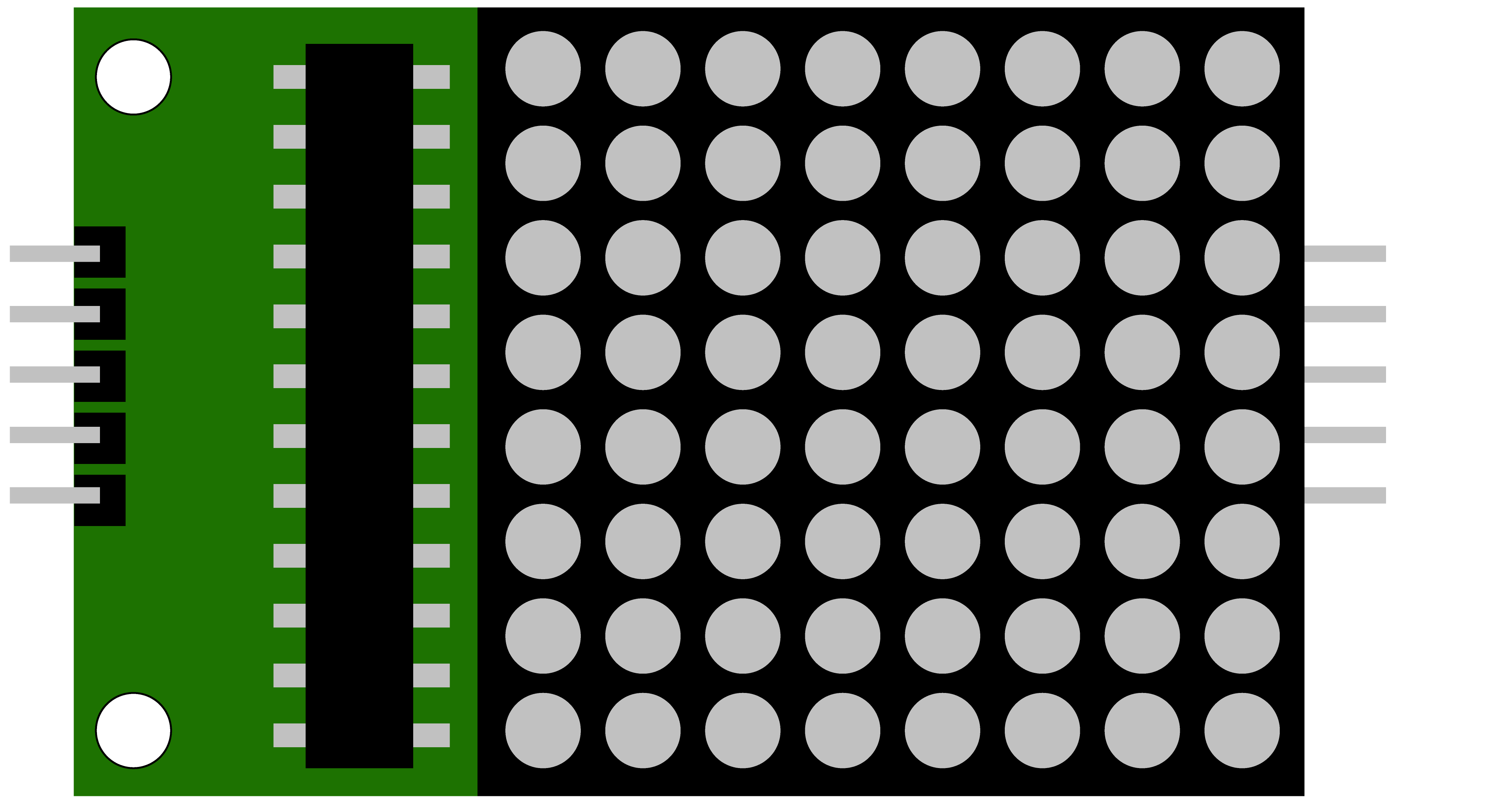
The 8x8 LED Matrix by DD Electronics is a versatile display component that consists of 64 LEDs arranged in an 8 by 8 grid. This matrix allows for the display of text, numbers, and simple graphics by individually controlling each LED. It is widely used in electronic displays, gaming devices, signage, and DIY projects where visual output is required.

Explore Projects Built with 8*8 matrix

Use Cirkit Designer to design, explore, and prototype these projects online. Some projects support real-time simulation. Click "Open Project" to start designing instantly!
Arduino UNO-Based Interactive LED Game with 8x8 Matrix and TM1637 Display
Image of Gra_na_refleks: A project utilizing 8*8 matrix in a practical application
This circuit is a game system controlled by an Arduino UNO, featuring an 8x8 LED matrix, a 4x4 keypad, and a TM1637 4-digit display. The user interacts with the game via the keypad, and the game state is displayed on the LED matrix and the TM1637 display, with power supplied by a 9V battery.
Cirkit Designer LogoOpen Project in Cirkit Designer
Arduino UNO Controlled LED Matrix Display with Interactive Pushbuttons
Image of Cykel: A project utilizing 8*8 matrix in a practical application
This circuit features an Arduino UNO microcontroller connected to multiple 8x8 LED matrix displays and pushbuttons. The pushbuttons are interfaced with digital pins D2, D3, and D4 on the Arduino for input, while the LED matrices are connected to digital pins D5 through D10 for control signals. Additionally, there is a single red LED with a series resistor connected to pin D12, likely used as an indicator light.
Cirkit Designer LogoOpen Project in Cirkit Designer
ESP8266 NodeMCU Controlled 8x8 LED Matrix Display
Image of Nodemcu: A project utilizing 8*8 matrix in a practical application
This circuit connects an ESP8266 NodeMCU microcontroller to an 8x8 LED matrix display. The NodeMCU controls the matrix using digital pins D5, D7, and D8 for chip select (CS), data input (DIN), and clock (CLK) signals, respectively. The circuit is designed to display patterns or characters on the LED matrix, which are driven by the microcontroller.
Cirkit Designer LogoOpen Project in Cirkit Designer
Arduino UNO Controlled LED Matrix and LCD Interface with Joystick Interaction
Image of Digital Game Circuit: A project utilizing 8*8 matrix in a practical application
This circuit features an Arduino UNO microcontroller interfaced with an 8x8 LED matrix, an LCD screen, and a KY-023 Dual Axis Joystick Module. The Arduino controls the LED matrix via digital pins D10-D12 and powers the matrix, LCD, and joystick module from its 5V output. The joystick's analog outputs are connected to the Arduino's analog inputs A0 and A1 for position sensing, while the LCD is controlled through digital pins D2-D6 and D13 for display purposes.
Cirkit Designer LogoOpen Project in Cirkit Designer

Explore Projects Built with 8*8 matrix

Use Cirkit Designer to design, explore, and prototype these projects online. Some projects support real-time simulation. Click "Open Project" to start designing instantly!
Image of Gra_na_refleks: A project utilizing 8*8 matrix in a practical application
Arduino UNO-Based Interactive LED Game with 8x8 Matrix and TM1637 Display
This circuit is a game system controlled by an Arduino UNO, featuring an 8x8 LED matrix, a 4x4 keypad, and a TM1637 4-digit display. The user interacts with the game via the keypad, and the game state is displayed on the LED matrix and the TM1637 display, with power supplied by a 9V battery.
Cirkit Designer LogoOpen Project in Cirkit Designer
Image of Cykel: A project utilizing 8*8 matrix in a practical application
Arduino UNO Controlled LED Matrix Display with Interactive Pushbuttons
This circuit features an Arduino UNO microcontroller connected to multiple 8x8 LED matrix displays and pushbuttons. The pushbuttons are interfaced with digital pins D2, D3, and D4 on the Arduino for input, while the LED matrices are connected to digital pins D5 through D10 for control signals. Additionally, there is a single red LED with a series resistor connected to pin D12, likely used as an indicator light.
Cirkit Designer LogoOpen Project in Cirkit Designer
Image of Nodemcu: A project utilizing 8*8 matrix in a practical application
ESP8266 NodeMCU Controlled 8x8 LED Matrix Display
This circuit connects an ESP8266 NodeMCU microcontroller to an 8x8 LED matrix display. The NodeMCU controls the matrix using digital pins D5, D7, and D8 for chip select (CS), data input (DIN), and clock (CLK) signals, respectively. The circuit is designed to display patterns or characters on the LED matrix, which are driven by the microcontroller.
Cirkit Designer LogoOpen Project in Cirkit Designer
Image of Digital Game Circuit: A project utilizing 8*8 matrix in a practical application
Arduino UNO Controlled LED Matrix and LCD Interface with Joystick Interaction
This circuit features an Arduino UNO microcontroller interfaced with an 8x8 LED matrix, an LCD screen, and a KY-023 Dual Axis Joystick Module. The Arduino controls the LED matrix via digital pins D10-D12 and powers the matrix, LCD, and joystick module from its 5V output. The joystick's analog outputs are connected to the Arduino's analog inputs A0 and A1 for position sensing, while the LCD is controlled through digital pins D2-D6 and D13 for display purposes.
Cirkit Designer LogoOpen Project in Cirkit Designer

Common Applications and Use Cases

  • Digital clocks and timers
  • Scrolling text displays
  • Simple games and animations
  • Interactive art installations
  • Educational tools for learning electronics and programming

Technical Specifications

Key Technical Details

  • Operating Voltage: 5V DC
  • Maximum Current (per LED): 20mA
  • Maximum Power (per LED): 100mW
  • LED Wavelength/Color: 625nm (Red)
  • Viewing Angle: 120 degrees

Pin Configuration and Descriptions

Pin Number Name Description
1 Vcc Power supply (5V)
2 GND Ground
3-10 An1-An8 Anode pins for rows 1-8
11-18 Cath1-Cath8 Cathode pins for columns 1-8

Usage Instructions

How to Use the Component in a Circuit

  1. Connect the Vcc pin to a 5V power supply and the GND pin to the ground.
  2. Interface the anode and cathode pins to a microcontroller or LED driver IC to control individual LEDs.
  3. Use current-limiting resistors on either the anode or cathode side to prevent LED damage.

Important Considerations and Best Practices

  • Ensure that the current through each LED does not exceed 20mA.
  • Multiplexing may be required to control all 64 LEDs with a limited number of microcontroller pins.
  • Use a proper refresh rate to avoid flickering when multiplexing.
  • Avoid static images for extended periods to prevent uneven LED wear.

Example Code for Arduino UNO

#include <LedControl.h>

// Pin configuration for the MAX7219 chip
int DIN_PIN = 7;
int CS_PIN = 6;
int CLK_PIN = 5;

// Create a new LedControl instance
LedControl lc = LedControl(DIN_PIN, CLK_PIN, CS_PIN, 1);

void setup() {
  // Initialize the display
  lc.shutdown(0, false);
  lc.setIntensity(0, 8);
  lc.clearDisplay(0);
}

void loop() {
  // Display a simple pattern
  for (int row = 0; row < 8; row++) {
    for (int col = 0; col < 8; col++) {
      lc.setLed(0, row, col, true); // Turn on LED at (row, col)
      delay(100);
      lc.setLed(0, row, col, false); // Turn off LED at (row, col)
    }
  }
}

Note: The above code uses the LedControl library for Arduino, which can be installed via the Arduino Library Manager. The library simplifies the process of controlling the 8x8 LED Matrix with a MAX7219 driver.

Troubleshooting and FAQs

Common Issues Users Might Face

  • LEDs not lighting up: Check the power supply and connections. Ensure that the pins are correctly connected to the microcontroller.
  • Flickering display: This may be due to a low refresh rate. Increase the refresh rate in your code.
  • Uneven brightness: Ensure that all LEDs have current-limiting resistors of the same value.

Solutions and Tips for Troubleshooting

  • Double-check wiring, especially the orientation of the anode and cathode pins.
  • Use a multimeter to verify that each LED is receiving the correct voltage.
  • If using multiplexing, ensure that the code correctly addresses each row and column.

FAQs:

  • Q: Can I use a different microcontroller instead of an Arduino UNO?

    • A: Yes, the 8x8 LED Matrix can be used with any microcontroller that provides sufficient I/O pins and can operate at 5V.
  • Q: How can I display characters or custom graphics?

    • A: You can create a bitmap for each character or graphic and write a function to map these to the LED matrix.
  • Q: What is the lifespan of the LEDs in the matrix?

    • A: The LEDs typically have a lifespan of 50,000 hours when operated within their rated current and voltage.

Remember to always follow the manufacturer's guidelines and datasheet for the most accurate and detailed information regarding the component.