How to Use RFID_Breakout_v2: Examples, Pinouts, and Specs
Introduction
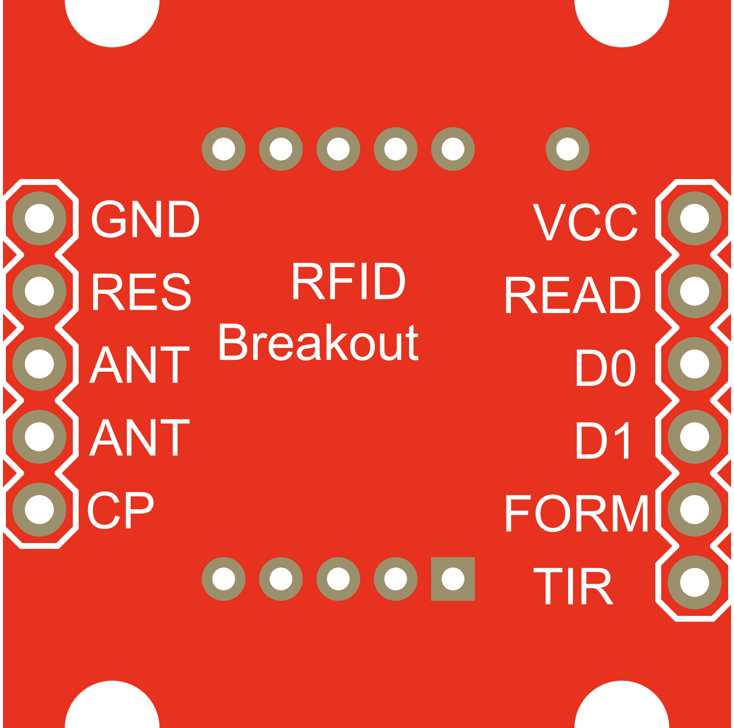
The RFID_Breakout_v2 is a versatile breakout board designed for the MFRC522 RFID (Radio-Frequency Identification) reader module. This component is widely used in applications that require wireless communication with RFID tags and cards. Common use cases include access control systems, asset tracking, and personal identification projects.
Explore Projects Built with RFID_Breakout_v2

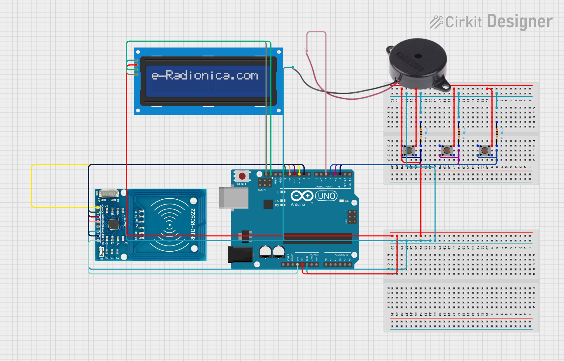
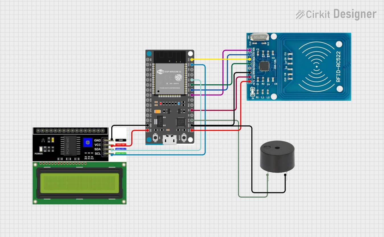
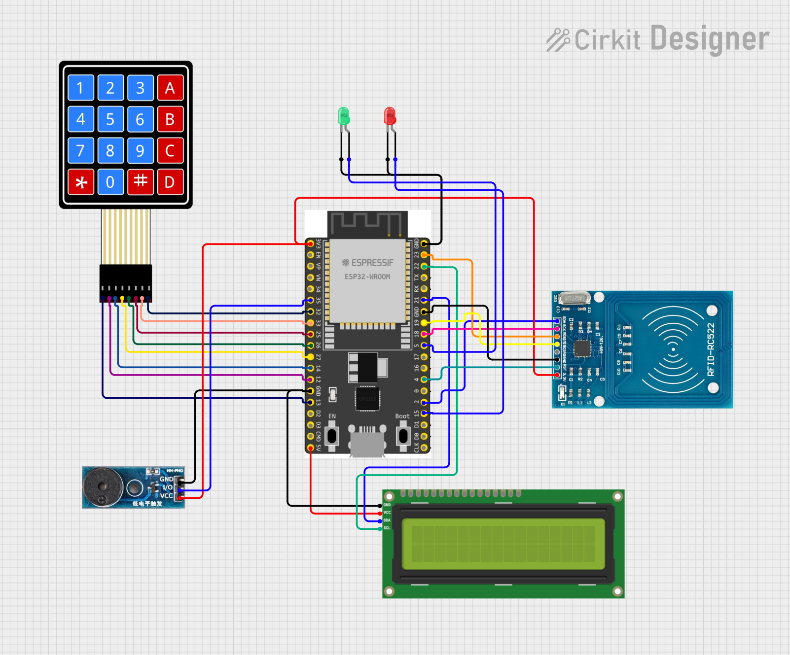
Explore Projects Built with RFID_Breakout_v2
Technical Specifications
Key Technical Details
- Supply Voltage: 3.3V
- Operating Current: 13-26mA
- Operating Frequency: 13.56MHz
- Supported Card Types: MIFARE Classic, MIFARE Ultralight, MIFARE DESFire, and more
- Communication Interface: SPI
- Reading Distance: Up to 50mm (depending on the antenna and card/tag type)
- Operating Temperature Range: -20°C to +80°C
Pin Configuration and Descriptions
| Pin Name | Description |
|---|---|
| SDA | Serial Data Signal for SPI |
| SCK | Serial Clock for SPI |
| MOSI | Master Out Slave In for SPI |
| MISO | Master In Slave Out for SPI |
| IRQ | Interrupt Request (not used in most cases) |
| GND | Ground |
| RST | Reset Signal |
| 3.3V | Supply Voltage |
Usage Instructions
Interfacing with a Circuit
To use the RFID_Breakout_v2 in a circuit:
- Connect the
3.3VandGNDpins to a 3.3V power supply and ground, respectively. - Interface the SPI pins (
SDA,SCK,MOSI,MISO) with the corresponding SPI pins of your microcontroller (e.g., Arduino UNO). - The
RSTpin should be connected to a digital pin on the microcontroller to control the reset function. - The
IRQpin is typically not used but can be connected if interrupt-driven operation is required.
Important Considerations and Best Practices
- Ensure that the power supply is 3.3V, as higher voltages may damage the module.
- Keep the RFID antenna area clear of metal surfaces to avoid interference with the RF field.
- For reliable communication, ensure that the SPI bus is not shared with other high-speed devices.
- Use proper decoupling capacitors close to the power supply pins to minimize power supply noise.
Example Code for Arduino UNO
#include <SPI.h>
#include <MFRC522.h>

#define RST_PIN         9     // Configurable, see typical pin layout above
#define SS_PIN          10    // Configurable, see typical pin layout above

MFRC522 mfrc522(SS_PIN, RST_PIN);  // Create MFRC522 instance

void setup() {
  Serial.begin(9600);   // Initialize serial communications with the PC
  SPI.begin();          // Init SPI bus
  mfrc522.PCD_Init();   // Init MFRC522 card
  Serial.println(F("Scan PICC to see UID and type..."));
}

void loop() {
  // Look for new cards
  if ( ! mfrc522.PICC_IsNewCardPresent() || ! mfrc522.PICC_ReadCardSerial() ) {
    delay(50);
    return;
  }

  // Show some details of the PICC (that is: the tag/card)
  Serial.print(F("Card UID:"));
  for (byte i = 0; i < mfrc522.uid.size; i++) {
    Serial.print(mfrc522.uid.uidByte[i] < 0x10 ? " 0" : " ");
    Serial.print(mfrc522.uid.uidByte[i], HEX);
  }
  Serial.println();
  // Additional card information can be included here

  // Halt PICC
  mfrc522.PICC_HaltA();
  // Stop encryption on PCD
  mfrc522.PCD_StopCrypto1();
}
Troubleshooting and FAQs
Common Issues
- RFID reader is not detecting tags: Ensure that the antenna area is clear of metal and that the RFID tags are compatible with the reader.
- Communication errors with the microcontroller: Check the wiring of the SPI interface and ensure that the correct pins are used.
- Intermittent functionality: Verify that the power supply is stable and that decoupling capacitors are in place.
Solutions and Tips for Troubleshooting
- Double-check the connections and solder joints on the breakout board for any cold solder or loose wires.
- Use the
Serial Monitorin the Arduino IDE to debug and check for error messages or status updates from the RFID reader. - If using multiple SPI devices, ensure that each device has a unique SS (Slave Select) pin and that only one device is active at a time.
FAQs
Q: Can I use the RFID_Breakout_v2 with a 5V microcontroller like Arduino UNO? A: Yes, but ensure that the RFID_Breakout_v2 is powered with 3.3V and that logic level conversion is used for the SPI interface if necessary.
Q: How can I increase the reading distance of the RFID_Breakout_v2? A: The reading distance can be affected by the antenna design, tag type, and environmental factors. Using a larger antenna and ensuring a clear RF path can help increase the reading distance.
Q: What should I do if the RFID_Breakout_v2 gets hot during operation? A: The RFID_Breakout_v2 should not get excessively hot. If it does, immediately disconnect the power and check for any issues with the power supply or potential shorts on the board.