How to Use 60x60x20 Fan 24V: Examples, Pinouts, and Specs
Introduction
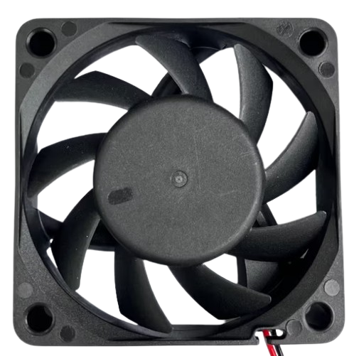
The 60x60x20 Fan 24V is a compact axial fan designed to operate at a nominal voltage of 24 volts. With dimensions of 60mm x 60mm x 20mm, this fan is ideal for cooling electronic components or providing ventilation in enclosures. Its small size makes it suitable for applications where space is limited, while its reliable performance ensures efficient heat dissipation.
Explore Projects Built with 60x60x20 Fan 24V


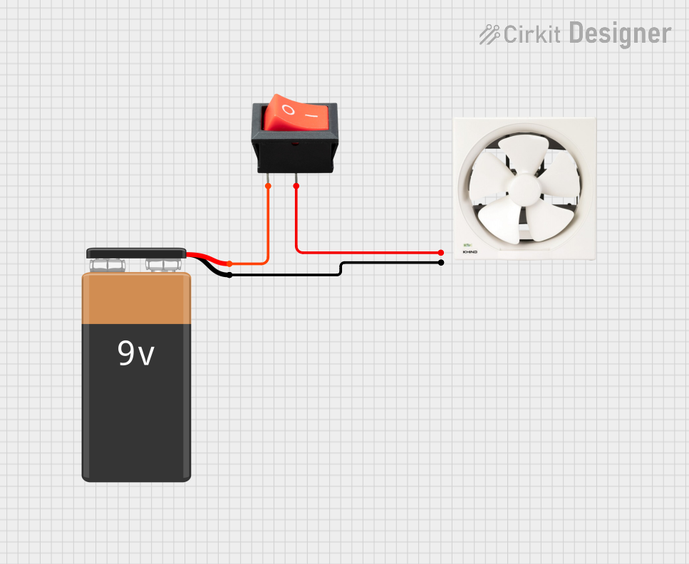
Explore Projects Built with 60x60x20 Fan 24V
Common Applications
- Cooling for power supplies, CPUs, and other electronic components
- Ventilation in small enclosures or cabinets
- Heat management in 3D printers, robotics, and industrial equipment
- General-purpose airflow in compact systems
Technical Specifications
Key Technical Details
| Parameter | Value |
|---|---|
| Dimensions | 60mm x 60mm x 20mm |
| Rated Voltage | 24V DC |
| Operating Voltage Range | 12V - 26.4V DC |
| Rated Current | 0.1A - 0.2A (depending on model) |
| Power Consumption | 2.4W - 4.8W |
| Airflow | ~20-30 CFM (Cubic Feet per Minute) |
| Speed | ~3000-5000 RPM (varies by model) |
| Noise Level | ~25-35 dBA |
| Bearing Type | Sleeve or Ball Bearing |
| Connector Type | 2-pin or 3-pin (depending on model) |
| Weight | ~50g |
Pin Configuration and Descriptions
2-Pin Connector
| Pin Number | Wire Color | Description |
|---|---|---|
| 1 | Red | Positive (+) Power Supply |
| 2 | Black | Ground (-) |
3-Pin Connector
| Pin Number | Wire Color | Description |
|---|---|---|
| 1 | Red | Positive (+) Power Supply |
| 2 | Black | Ground (-) |
| 3 | Yellow | Tachometer (Speed Feedback) |
Usage Instructions
How to Use the Fan in a Circuit
- Power Supply: Ensure the fan is connected to a 24V DC power source. If using a lower voltage (e.g., 12V), the fan may operate at reduced speed and airflow.
- Wiring:
- For a 2-pin fan, connect the red wire to the positive terminal of the power supply and the black wire to the ground.
- For a 3-pin fan, connect the red and black wires as above. The yellow wire can be connected to a microcontroller or monitoring circuit to read the fan's speed (optional).
- Mounting: Secure the fan using screws or adhesive mounts. Ensure proper airflow direction by checking the arrow markings on the fan housing.
- Testing: Power on the circuit and verify that the fan spins smoothly without unusual noise or vibration.
Important Considerations and Best Practices
- Voltage Tolerance: Do not exceed the maximum operating voltage of 26.4V, as this may damage the fan.
- Airflow Direction: The fan typically blows air in the direction of the arrow on its housing. Install it accordingly for optimal cooling.
- Noise Reduction: Use rubber mounts or grommets to minimize vibration and noise.
- Dust and Maintenance: Periodically clean the fan blades and housing to prevent dust buildup, which can reduce efficiency and increase noise.
- Tachometer Usage: If using the 3-pin version, connect the yellow wire to a microcontroller (e.g., Arduino) to monitor the fan's speed.
Example: Connecting to an Arduino UNO
If you are using a 3-pin fan and want to monitor its speed, you can connect the tachometer wire to an Arduino UNO. Below is an example code snippet:
// Example code to read fan speed using Arduino UNO
// Connect the fan's yellow wire (tachometer) to pin 2 on the Arduino
// Red wire to 24V power supply, black wire to ground

const int tachPin = 2;  // Tachometer signal pin
volatile int fanPulseCount = 0;  // Counter for tachometer pulses

void setup() {
  pinMode(tachPin, INPUT_PULLUP);  // Set tachometer pin as input
  attachInterrupt(digitalPinToInterrupt(tachPin), countPulses, FALLING);
  Serial.begin(9600);  // Initialize serial communication
}

void loop() {
  delay(1000);  // Wait for 1 second
  int rpm = (fanPulseCount / 2) * 60;  // Calculate RPM (2 pulses per revolution)
  fanPulseCount = 0;  // Reset pulse count
  Serial.print("Fan Speed: ");
  Serial.print(rpm);
  Serial.println(" RPM");
}

// Interrupt service routine to count tachometer pulses
void countPulses() {
  fanPulseCount++;
}
Notes:
- Ensure the Arduino is powered separately from the fan's 24V power supply.
- Use a level shifter or resistor divider if the tachometer signal exceeds 5V.
Troubleshooting and FAQs
Common Issues and Solutions
| Issue | Possible Cause | Solution |
|---|---|---|
| Fan does not spin | No power or incorrect wiring | Check power supply and wiring |
| Fan spins slowly | Insufficient voltage | Ensure 24V is supplied to the fan |
| Excessive noise or vibration | Loose mounting or dust buildup | Tighten screws and clean the fan |
| Tachometer signal not working | Incorrect connection or damaged wire | Verify wiring and check signal levels |
FAQs
Q: Can I use this fan with a 12V power supply?
A: Yes, but the fan will operate at reduced speed and airflow. For optimal performance, use a 24V power supply.
Q: How do I determine the airflow direction?
A: Look for the arrow markings on the fan housing. One arrow indicates airflow direction, and the other indicates blade rotation.
Q: Can I control the fan speed?
A: Speed control is possible using a PWM (Pulse Width Modulation) signal, but this requires additional circuitry or a compatible fan model.
Q: Is the fan waterproof?
A: Most 60x60x20 fans are not waterproof. Check the IP rating of your specific model if water resistance is required.
Q: How often should I clean the fan?
A: Clean the fan every 3-6 months, or more frequently in dusty environments, to maintain optimal performance.