How to Use MDD20A CYTRON MOTOR DRIVER: Examples, Pinouts, and Specs
Introduction
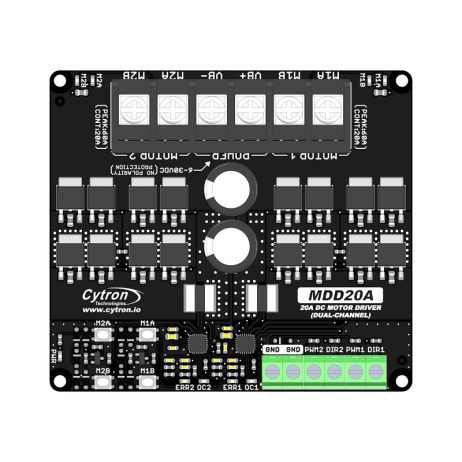
The MDD20A is a dual-channel motor driver designed for controlling DC motors and stepper motors. It is capable of handling up to 20A of continuous current per channel, making it ideal for high-power motor control applications. The driver features built-in protection mechanisms, including overcurrent and thermal overload protection, ensuring reliable operation even under demanding conditions. Its compact design and ease of use make it a popular choice for robotics, automation, and other motor control projects.
Explore Projects Built with MDD20A CYTRON MOTOR DRIVER


Explore Projects Built with MDD20A CYTRON MOTOR DRIVER
Common Applications
- Robotics (e.g., controlling robot wheels or arms)
- Automation systems
- Electric vehicles and carts
- Conveyor belts
- Stepper motor control for CNC machines or 3D printers
Technical Specifications
Key Specifications
- Input Voltage Range: 7V to 30V DC
- Continuous Current: 20A per channel
- Peak Current: 30A per channel (for short durations)
- Control Signals: PWM (Pulse Width Modulation) and Direction
- PWM Frequency: Up to 20kHz
- Logic Voltage: 3.3V or 5V compatible
- Protection Features: Overcurrent, thermal shutdown, and undervoltage lockout
- Dimensions: 84mm x 62mm x 25mm
- Weight: Approximately 100g
Pin Configuration and Descriptions
The MDD20A has two sets of input pins for motor control and two sets of output terminals for connecting motors. Below is the pin configuration:
Input Pins
| Pin Name | Description |
|---|---|
| PWM1 | PWM input for Motor 1. Controls the speed of Motor 1. |
| DIR1 | Direction input for Motor 1. Sets the rotation direction of Motor 1. |
| PWM2 | PWM input for Motor 2. Controls the speed of Motor 2. |
| DIR2 | Direction input for Motor 2. Sets the rotation direction of Motor 2. |
| GND | Ground connection for logic signals. |
| VCC | Logic voltage input (3.3V or 5V). |
Output Terminals
| Terminal Name | Description |
|---|---|
| M1A | Motor 1 output terminal A. Connect to one terminal of Motor 1. |
| M1B | Motor 1 output terminal B. Connect to the other terminal of Motor 1. |
| M2A | Motor 2 output terminal A. Connect to one terminal of Motor 2. |
| M2B | Motor 2 output terminal B. Connect to the other terminal of Motor 2. |
| VM | Power supply input for motors (7V to 30V DC). |
| GND | Ground connection for motor power. |
Usage Instructions
How to Use the MDD20A in a Circuit
- Power Supply: Connect a DC power supply (7V to 30V) to the VM and GND terminals. Ensure the power supply can provide sufficient current for your motors.
- Motor Connections: Connect the motors to the output terminals (M1A, M1B, M2A, M2B). For DC motors, the polarity determines the default rotation direction.
- Logic Connections: Connect the control signals (PWM1, DIR1, PWM2, DIR2) to a microcontroller or other control device. Ensure the logic voltage matches the microcontroller's output (3.3V or 5V).
- Grounding: Connect the GND pin of the MDD20A to the ground of your microcontroller to ensure a common reference.
Important Considerations
- Use appropriate heat dissipation methods (e.g., heatsinks or fans) if operating near the maximum current rating.
- Ensure the power supply voltage does not exceed 30V to avoid damaging the driver.
- Use a fuse or circuit breaker to protect the motor driver and connected components from overcurrent conditions.
- For stepper motors, use both channels of the MDD20A to control the two motor coils.
Example: Controlling a DC Motor with Arduino UNO
Below is an example of how to control a single DC motor using the MDD20A and an Arduino UNO:
// Define control pins for Motor 1
const int pwmPin = 9;  // PWM signal for speed control
const int dirPin = 8;  // Direction control

void setup() {
  // Set pin modes
  pinMode(pwmPin, OUTPUT);
  pinMode(dirPin, OUTPUT);
}

void loop() {
  // Rotate motor in one direction
  digitalWrite(dirPin, HIGH);  // Set direction
  analogWrite(pwmPin, 128);    // Set speed (0-255, 128 = 50% duty cycle)
  delay(2000);                 // Run for 2 seconds

  // Stop motor
  analogWrite(pwmPin, 0);      // Set speed to 0
  delay(1000);                 // Wait for 1 second

  // Rotate motor in the opposite direction
  digitalWrite(dirPin, LOW);   // Change direction
  analogWrite(pwmPin, 200);    // Set speed (200 = ~78% duty cycle)
  delay(2000);                 // Run for 2 seconds

  // Stop motor
  analogWrite(pwmPin, 0);      // Set speed to 0
  delay(1000);                 // Wait for 1 second
}
Notes:
- Adjust the
pwmPinanddirPinvalues to match your wiring. - The
analogWritefunction sets the motor speed, where 0 is off and 255 is full speed.
Troubleshooting and FAQs
Common Issues
Motor Not Spinning
- Cause: Incorrect wiring or insufficient power supply.
- Solution: Double-check all connections and ensure the power supply meets the voltage and current requirements.
Overheating
- Cause: Operating near or above the maximum current rating without proper cooling.
- Solution: Add a heatsink or fan to the motor driver and reduce the motor load if possible.
Erratic Motor Behavior
- Cause: Noise or interference in the control signals.
- Solution: Use shielded cables for control signals and ensure proper grounding.
Driver Not Responding
- Cause: Logic voltage mismatch or damaged components.
- Solution: Verify the logic voltage (3.3V or 5V) and inspect the driver for physical damage.
FAQs
Can the MDD20A control stepper motors?
- Yes, the MDD20A can control stepper motors by using both channels to drive the two motor coils.
What is the maximum PWM frequency supported?
- The MDD20A supports PWM frequencies up to 20kHz.
Can I use the MDD20A with a 3.3V microcontroller?
- Yes, the MDD20A is compatible with both 3.3V and 5V logic levels.
Is reverse polarity protection included?
- No, the MDD20A does not have reverse polarity protection. Ensure correct power supply polarity to avoid damage.