How to Use Terminal PCB 2 Pin: Examples, Pinouts, and Specs
Introduction
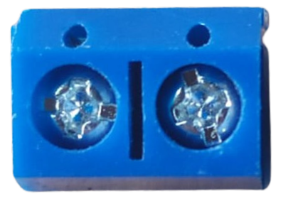
The Terminal PCB 2 Pin is a compact and reliable two-pin terminal block designed for printed circuit boards (PCBs). It provides a convenient way to connect and disconnect wires in electronic circuits without the need for soldering. This component is widely used in applications where secure and removable wire connections are required, such as power supplies, control systems, and prototyping.
Explore Projects Built with Terminal PCB 2 Pin


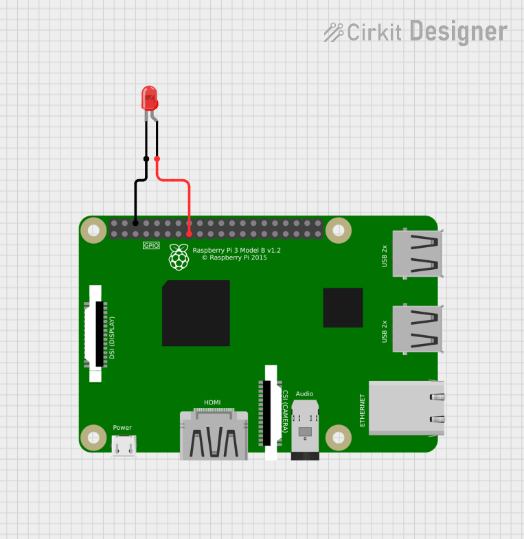

Explore Projects Built with Terminal PCB 2 Pin
Common Applications and Use Cases
- Power supply connections in PCBs
- Signal and data transmission in control systems
- Prototyping and testing circuits
- Industrial automation and robotics
- Audio and speaker connections
Technical Specifications
The Terminal PCB 2 Pin is designed to meet the needs of a variety of electronic applications. Below are its key technical details:
General Specifications
| Parameter | Value |
|---|---|
| Number of Pins | 2 |
| Rated Voltage | 300V AC/DC |
| Rated Current | 10A |
| Wire Size Compatibility | 26-12 AWG |
| Pitch (Pin Spacing) | 5.08 mm (0.2 inches) |
| Operating Temperature | -40°C to +105°C |
| Material | Flame-retardant thermoplastic |
| Contact Material | Nickel-plated brass |
Pin Configuration and Descriptions
| Pin Number | Description |
|---|---|
| 1 | Positive terminal (V+ or Signal) |
| 2 | Negative terminal (V- or Ground) |
Usage Instructions
The Terminal PCB 2 Pin is straightforward to use and can be integrated into a variety of circuits. Follow the steps below for proper usage:
How to Use the Component in a Circuit
Soldering the Terminal Block to the PCB:
- Align the terminal block's pins with the corresponding holes on the PCB.
- Ensure the terminal block is oriented correctly, with the wire entry points accessible.
- Solder the pins securely to the PCB pads, ensuring no cold solder joints.
Connecting Wires:
- Strip the insulation from the wire ends (approximately 5-7 mm).
- Insert the stripped wire ends into the terminal block's openings.
- Tighten the screws on the terminal block to secure the wires in place.
Testing the Connection:
- Verify the connections using a multimeter to ensure proper continuity.
- Power on the circuit and check for stable operation.
Important Considerations and Best Practices
- Wire Gauge: Ensure the wire gauge is within the supported range (26-12 AWG) for a secure connection.
- Tightening Screws: Do not overtighten the screws, as this may damage the wire or the terminal block.
- PCB Design: When designing the PCB, ensure the pin spacing (5.08 mm) matches the terminal block's pitch.
- Current Rating: Do not exceed the rated current (10A) to avoid overheating or damage.
- Environmental Conditions: Use the terminal block within the specified operating temperature range (-40°C to +105°C).
Example: Connecting to an Arduino UNO
The Terminal PCB 2 Pin can be used to connect external components, such as power supplies or sensors, to an Arduino UNO. Below is an example of how to use it for a 12V power supply connection:
Circuit Diagram
- Connect the positive terminal of the 12V power supply to Pin 1 (V+).
- Connect the negative terminal of the 12V power supply to Pin 2 (GND).
- Use the terminal block to securely attach the wires to the PCB.
Arduino Code Example
// Example code to read a sensor connected via the Terminal PCB 2 Pin
// Ensure the sensor's V+ and GND are connected to the terminal block

const int sensorPin = A0; // Analog pin connected to the sensor output

void setup() {
  Serial.begin(9600); // Initialize serial communication
  pinMode(sensorPin, INPUT); // Set the sensor pin as input
}

void loop() {
  int sensorValue = analogRead(sensorPin); // Read the sensor value
  Serial.print("Sensor Value: ");
  Serial.println(sensorValue); // Print the sensor value to the Serial Monitor
  delay(1000); // Wait for 1 second before the next reading
}
Troubleshooting and FAQs
Common Issues and Solutions
| Issue | Possible Cause | Solution |
|---|---|---|
| Loose wire connections | Screws not tightened properly | Tighten the screws securely. |
| Intermittent connection | Poor soldering or damaged wires | Resolder the pins or replace wires. |
| Overheating of the terminal block | Exceeding the rated current (10A) | Reduce the current to within limits. |
| Difficulty inserting wires | Wire gauge not compatible | Use wires within the 26-12 AWG range. |
FAQs
Can I use this terminal block for AC connections?
- Yes, the Terminal PCB 2 Pin supports both AC and DC connections up to 300V.
What tools are required to use this component?
- You will need a soldering iron, screwdriver, wire stripper, and multimeter.
Can I use this terminal block for high-frequency signals?
- While it can handle low-frequency signals, it is not ideal for high-frequency applications due to potential signal degradation.
Is the terminal block reusable?
- Yes, the terminal block can be reused as long as it is not physically damaged.
By following this documentation, you can effectively integrate the Terminal PCB 2 Pin into your electronic projects for secure and reliable wire connections.