How to Use servo1: Examples, Pinouts, and Specs
Introduction
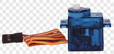
Servo1 is a servo motor designed to provide precise control of angular position. It is widely used in robotics, automation, and other applications requiring controlled movement. Servo1 operates by receiving a Pulse Width Modulation (PWM) signal, which determines its angular position. Its compact size and reliability make it ideal for projects such as robotic arms, pan-tilt camera systems, and RC vehicles.
Explore Projects Built with servo1

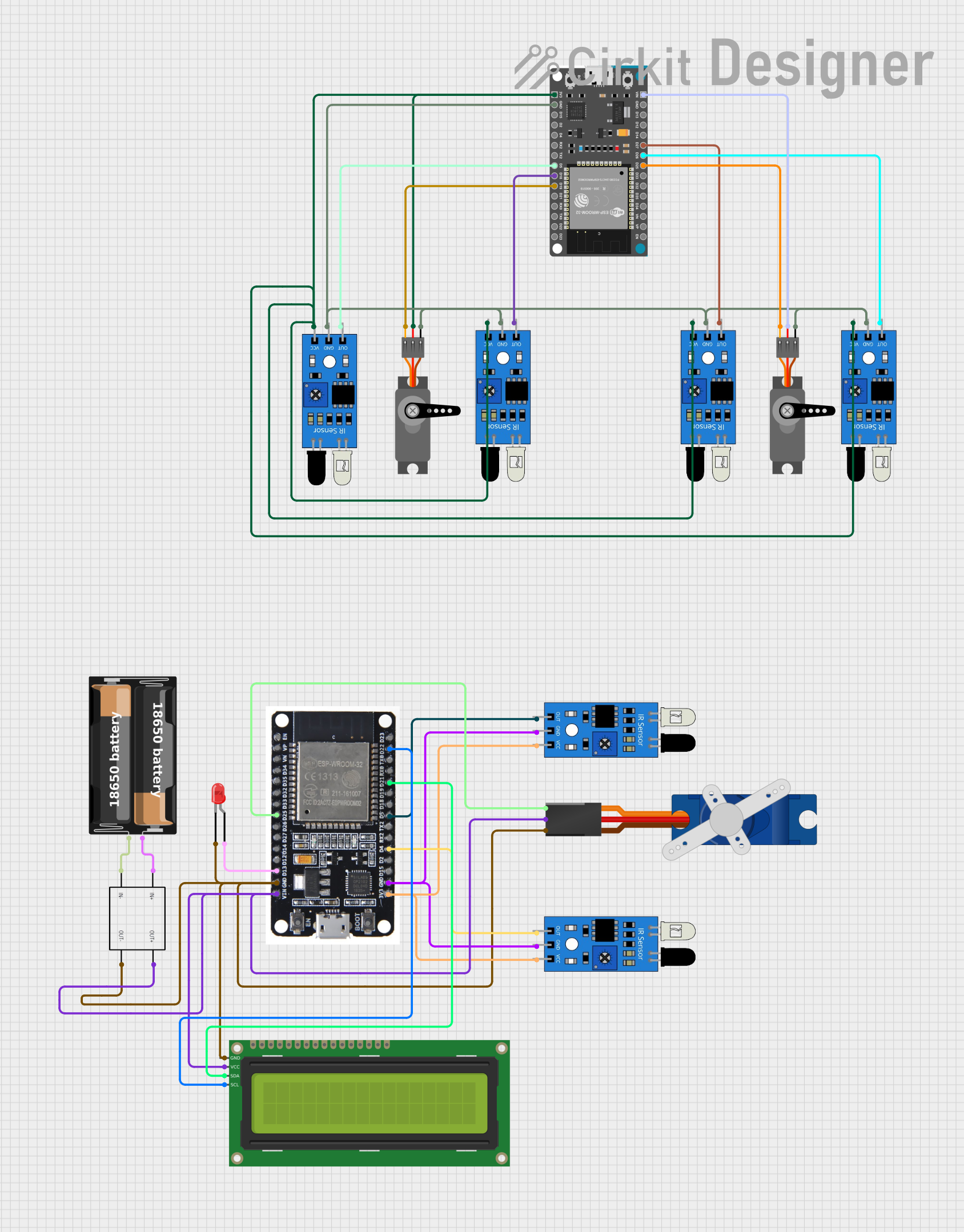
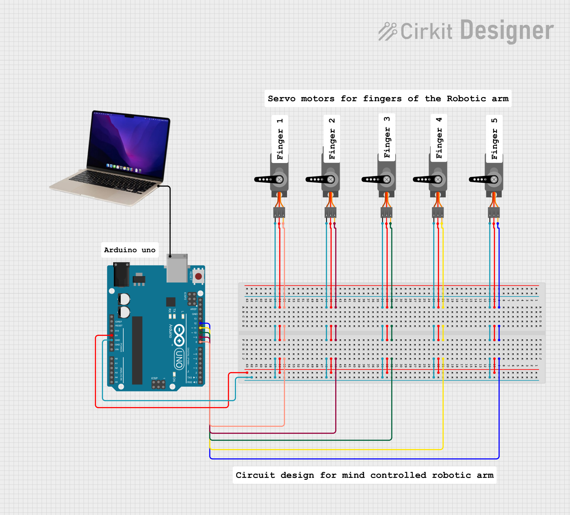
Explore Projects Built with servo1
Technical Specifications
- Operating Voltage: 4.8V to 6V
- Operating Current: 100mA to 250mA (depending on load)
- Stall Current: ~1A (at 6V)
- Torque: 2.5 kg·cm (at 4.8V), 3.0 kg·cm (at 6V)
- Operating Speed: 0.12 sec/60° (at 6V)
- Control Signal: PWM (Pulse Width Modulation)
- PWM Frequency: 50 Hz
- Angle Range: 0° to 180°
- Dimensions: 40mm x 20mm x 36mm
- Weight: 45g
Pin Configuration and Descriptions
| Pin Number | Pin Name | Description |
|---|---|---|
| 1 | Signal | Receives the PWM signal to control the angular position of the servo motor. |
| 2 | VCC | Power supply pin (4.8V to 6V). Connect to a regulated power source. |
| 3 | GND | Ground pin. Connect to the ground of the power supply and control circuit. |
Usage Instructions
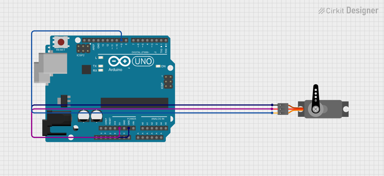
How to Use Servo1 in a Circuit
- Power Connection: Connect the VCC pin to a 5V or 6V regulated power supply. Ensure the power supply can handle the current requirements of the servo motor.
- Ground Connection: Connect the GND pin to the ground of the power supply and the control circuit.
- Signal Connection: Connect the Signal pin to a PWM-capable pin of a microcontroller (e.g., Arduino UNO).
- PWM Signal: Generate a PWM signal with a frequency of 50 Hz. The duty cycle of the signal determines the angular position:
- 1 ms pulse width corresponds to 0°.
- 1.5 ms pulse width corresponds to 90°.
- 2 ms pulse width corresponds to 180°.
Important Considerations and Best Practices
- Use a separate power supply for the servo motor if it draws significant current, as this prevents voltage drops that could affect the microcontroller.
- Avoid stalling the servo motor for extended periods, as this can cause overheating and damage.
- Use capacitors across the power supply to reduce noise and voltage fluctuations.
- Ensure the PWM signal is stable and within the specified frequency range (50 Hz).
Example Code for Arduino UNO
Below is an example of how to control Servo1 using an Arduino UNO:
#include <Servo.h> // Include the Servo library

Servo servo1; // Create a Servo object to control Servo1

void setup() {
  servo1.attach(9); // Attach Servo1 to pin 9 on the Arduino
}

void loop() {
  servo1.write(0); // Move Servo1 to 0 degrees
  delay(1000);     // Wait for 1 second

  servo1.write(90); // Move Servo1 to 90 degrees
  delay(1000);      // Wait for 1 second

  servo1.write(180); // Move Servo1 to 180 degrees
  delay(1000);       // Wait for 1 second
}
Troubleshooting and FAQs
Common Issues and Solutions
Servo1 is not moving:
- Ensure the power supply voltage is within the specified range (4.8V to 6V).
- Verify that the Signal pin is receiving a valid PWM signal.
- Check all connections for loose wires or poor soldering.
Servo1 jitters or moves erratically:
- Ensure the PWM signal is stable and has a frequency of 50 Hz.
- Use a capacitor (e.g., 100 µF) across the power supply to reduce noise.
- Check for interference from other components in the circuit.
Servo1 overheats:
- Avoid stalling the servo motor for extended periods.
- Ensure the load on the servo does not exceed its torque rating.
Servo1 does not reach the full 0° to 180° range:
- Verify that the PWM pulse width corresponds to the correct range (1 ms to 2 ms).
- Check for mechanical obstructions that may limit movement.
FAQs
Can Servo1 operate at 3.3V?
- No, Servo1 requires a minimum operating voltage of 4.8V. Using a lower voltage may result in erratic behavior or failure to operate.
Can I control multiple Servo1 motors with one Arduino?
- Yes, you can control multiple Servo1 motors using different PWM-capable pins on the Arduino. However, ensure the power supply can handle the combined current draw.
What happens if I send a PWM signal outside the specified range?
- Sending a PWM signal outside the 1 ms to 2 ms range may cause the servo to behave unpredictably or attempt to move beyond its physical limits, potentially damaging the motor.
By following this documentation, you can effectively integrate Servo1 into your projects and troubleshoot common issues.