
How to Use Adafruit DS1841: Examples, Pinouts, and Specs
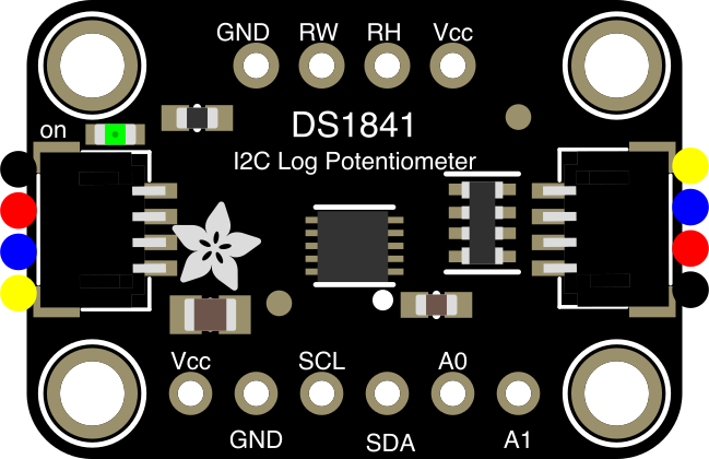
 Design with Adafruit DS1841 in Cirkit Designer
Introduction
The Adafruit DS1841 (Part ID: 4570) is a digital potentiometer designed for precise control of resistance in electronic circuits. Unlike traditional mechanical potentiometers, the DS1841 allows users to adjust resistance values programmatically via an I2C interface. This makes it an excellent choice for applications requiring dynamic or automated resistance adjustments.
Explore Projects Built with Adafruit DS1841
 Open Project in Cirkit Designer
 Open Project in Cirkit Designer
 Open Project in Cirkit Designer
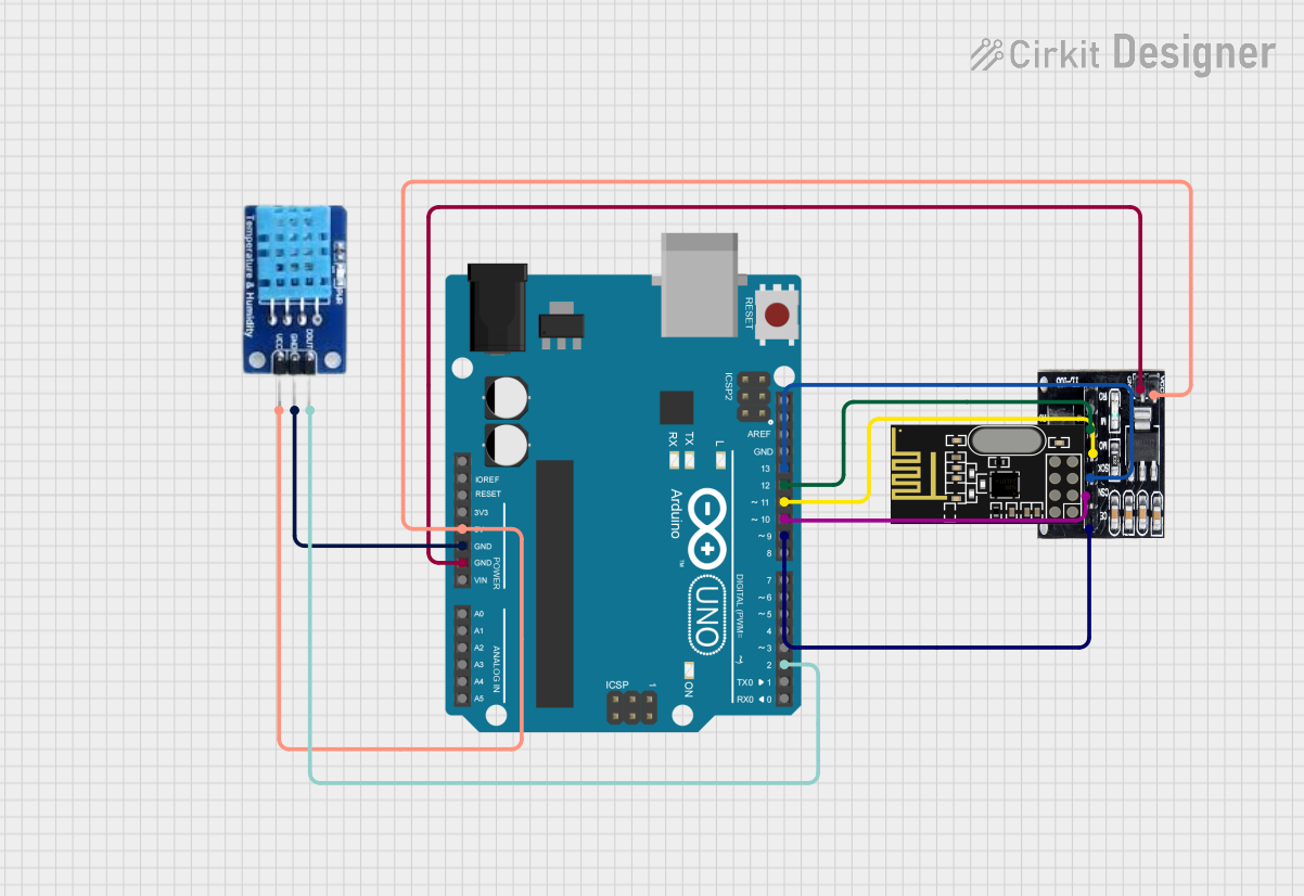 Open Project in Cirkit Designer
Explore Projects Built with Adafruit DS1841
Open Project in Cirkit DesignerOpen Project in Cirkit DesignerOpen Project in Cirkit DesignerOpen Project in Cirkit DesignerCommon Applications
- Audio volume control
- Sensor calibration and tuning
- Adjustable gain circuits
- LED dimming
- Programmable resistor networks
Technical Specifications
The Adafruit DS1841 is a versatile component with the following key specifications:
| Parameter | Value |
|---|---|
| Operating Voltage | 3.3V to 5V |
| Resistance Range | 10 kΩ (256 steps) |
| Communication Interface | I2C |
| I2C Address | 0x28 (default, configurable) |
| Operating Temperature | -40°C to +85°C |
| Wiper Memory | Non-volatile |
| Adjustment Method | Logarithmic |
Pin Configuration
The DS1841 comes with the following pinout:
| Pin | Name | Description |
|---|---|---|
| 1 | VIN | Power supply input (3.3V to 5V) |
| 2 | GND | Ground |
| 3 | SCL | I2C clock line |
| 4 | SDA | I2C data line |
| 5 | A0 | I2C address selection (connect to GND or VIN) |
| 6 | W | Wiper terminal (connect to the circuit requiring resistance adjustment) |
Usage Instructions
Connecting the DS1841
To use the Adafruit DS1841 in a circuit:
- Connect the VIN pin to a 3.3V or 5V power supply.
- Connect the GND pin to the ground of your circuit.
- Connect the SCL and SDA pins to the corresponding I2C pins on your microcontroller.
- Optionally, connect the A0 pin to GND or VIN to configure the I2C address.
- Connect the W pin to the circuit where variable resistance is required.
Important Considerations
- Ensure the power supply voltage matches the operating range (3.3V to 5V).
- Use pull-up resistors (typically 4.7 kΩ) on the I2C lines if your microcontroller does not have internal pull-ups.
- The DS1841 uses a logarithmic adjustment curve, making it ideal for audio and other applications requiring non-linear resistance changes.
Example: Using DS1841 with Arduino UNO
Below is an example of how to control the DS1841 using an Arduino UNO:
#include <Wire.h>

// I2C address of the DS1841 (default is 0x28)
#define DS1841_I2C_ADDRESS 0x28

void setup() {
  Wire.begin(); // Initialize I2C communication
  Serial.begin(9600); // Initialize serial communication for debugging

  // Set the wiper position to mid-range (128 out of 256)
  setWiperPosition(128);
}

void loop() {
  // Example: Gradually increase resistance
  for (int position = 0; position <= 255; position++) {
    setWiperPosition(position);
    delay(100); // Wait 100ms between steps
  }
}

// Function to set the wiper position
void setWiperPosition(uint8_t position) {
  Wire.beginTransmission(DS1841_I2C_ADDRESS);
  Wire.write(0x00); // Command to set wiper position
  Wire.write(position); // Desired wiper position (0-255)
  Wire.endTransmission();

  Serial.print("Wiper position set to: ");
  Serial.println(position);
}
Best Practices
- Avoid exceeding the maximum voltage and current ratings to prevent damage.
- Use decoupling capacitors (e.g., 0.1 µF) near the VIN pin to stabilize the power supply.
- If using multiple DS1841 devices on the same I2C bus, configure unique I2C addresses using the A0 pin.
Troubleshooting and FAQs
Common Issues
The DS1841 is not responding to I2C commands.
- Verify the I2C address (default is 0x28) and ensure it matches your code.
- Check the connections for the SCL and SDA pins.
- Ensure pull-up resistors are present on the I2C lines.
The resistance does not change as expected.
- Confirm that the wiper position is being set correctly in your code.
- Check the W pin connection to the circuit.
The component overheats or behaves erratically.
- Ensure the power supply voltage is within the 3.3V to 5V range.
- Verify that the current through the wiper does not exceed the maximum rating.
FAQs
Q: Can I use the DS1841 with a 3.3V microcontroller?
A: Yes, the DS1841 operates with both 3.3V and 5V logic levels, making it compatible with most microcontrollers.
Q: How many DS1841 devices can I connect to a single I2C bus?
A: You can connect up to two DS1841 devices by configuring the A0 pin to set unique I2C addresses.
Q: Does the DS1841 retain its wiper position after power is removed?
A: Yes, the DS1841 features non-volatile memory, so the wiper position is retained after power loss.
Q: Can I use the DS1841 for linear resistance adjustments?
A: The DS1841 uses a logarithmic adjustment curve, which is ideal for audio and other non-linear applications. For linear adjustments, consider a different digital potentiometer.
By following this documentation, you can effectively integrate the Adafruit DS1841 into your projects for precise and programmable resistance control.