
How to Use TLC5940 (HTSSOP-28 PowerPAD): Examples, Pinouts, and Specs
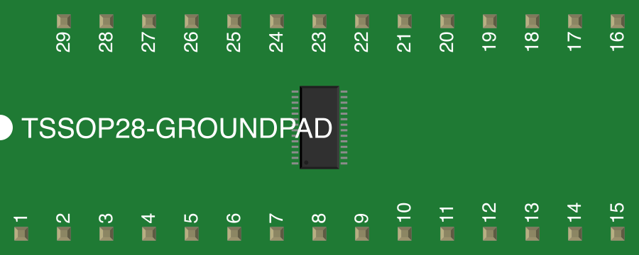
 Design with TLC5940 (HTSSOP-28 PowerPAD) in Cirkit Designer
Introduction
The TLC5940 is a 16-channel LED driver with built-in PWM (Pulse Width Modulation) control for each channel, enabling precise brightness control for LEDs. It is designed to drive multiple LEDs simultaneously, making it ideal for applications requiring dynamic lighting effects, such as LED displays, signage, and decorative lighting. The component features a serial interface for seamless communication with microcontrollers and is packaged in a compact HTSSOP-28 PowerPAD format, which ensures efficient thermal management during operation.
Explore Projects Built with TLC5940 (HTSSOP-28 PowerPAD)
 Open Project in Cirkit Designer
 Open Project in Cirkit Designer
 Open Project in Cirkit Designer
 Open Project in Cirkit Designer
Explore Projects Built with TLC5940 (HTSSOP-28 PowerPAD)
Open Project in Cirkit DesignerOpen Project in Cirkit DesignerOpen Project in Cirkit DesignerOpen Project in Cirkit DesignerCommon Applications:
- LED displays and matrices
- RGB LED lighting systems
- Decorative and architectural lighting
- Industrial control panels
- Automotive lighting systems
Technical Specifications
Key Technical Details:
- Number of Channels: 16
- PWM Resolution: 12-bit (4096 steps)
- Output Current per Channel: Up to 120 mA (programmable)
- Supply Voltage (Vcc): 3.0 V to 5.5 V
- Output Voltage (Vout): Up to 17 V
- Data Transfer Interface: Serial (SPI-like protocol)
- Thermal Management: PowerPAD for heat dissipation
- Package Type: HTSSOP-28 PowerPAD
- Operating Temperature Range: -40°C to 85°C
Pin Configuration and Descriptions:
The TLC5940 comes in a 28-pin HTSSOP package. Below is the pin configuration:
| Pin Number | Pin Name | Description |
|---|---|---|
| 1 | OUT0 | Channel 0 LED driver output |
| 2 | OUT1 | Channel 1 LED driver output |
| 3 | OUT2 | Channel 2 LED driver output |
| 4 | OUT3 | Channel 3 LED driver output |
| 5 | OUT4 | Channel 4 LED driver output |
| 6 | OUT5 | Channel 5 LED driver output |
| 7 | OUT6 | Channel 6 LED driver output |
| 8 | OUT7 | Channel 7 LED driver output |
| 9 | OUT8 | Channel 8 LED driver output |
| 10 | OUT9 | Channel 9 LED driver output |
| 11 | OUT10 | Channel 10 LED driver output |
| 12 | OUT11 | Channel 11 LED driver output |
| 13 | OUT12 | Channel 12 LED driver output |
| 14 | OUT13 | Channel 13 LED driver output |
| 15 | OUT14 | Channel 14 LED driver output |
| 16 | OUT15 | Channel 15 LED driver output |
| 17 | GND | Ground |
| 18 | VCC | Supply voltage (3.0 V to 5.5 V) |
| 19 | IREF | Reference current input for setting output current |
| 20 | SOUT | Serial data output for daisy-chaining multiple TLC5940 devices |
| 21 | SIN | Serial data input |
| 22 | SCLK | Serial clock input |
| 23 | XLAT | Latch signal input |
| 24 | BLANK | Blank signal input (disables all outputs when high) |
| 25 | DCPRG | DC programming input (used for dot correction) |
| 26 | VPRG | Mode selection input (switches between dot correction and grayscale mode) |
| 27 | GSCLK | Grayscale clock input |
| 28 | GND (PAD) | Thermal pad (must be connected to ground for proper heat dissipation) |
Usage Instructions
How to Use the TLC5940 in a Circuit:
Power Supply:
- Connect the VCC pin to a 3.0 V to 5.5 V power source.
- Connect the GND pins and the thermal pad to the ground.
Current Setting:
- Use a resistor connected to the IREF pin to set the maximum output current for all channels.
The current is calculated as:Iout = (1.24 V / Rref) × 31.5
whereRrefis the resistance in ohms.
- Use a resistor connected to the IREF pin to set the maximum output current for all channels.
Serial Communication:
- Connect the SIN, SCLK, and XLAT pins to the microcontroller for data transfer.
- Use the GSCLK pin to provide a grayscale clock signal for PWM control.
LED Connections:
- Connect the cathodes of the LEDs to the OUT0–OUT15 pins.
- The anodes of the LEDs should be connected to a suitable power source through a current-limiting resistor if required.
Daisy-Chaining:
- To control multiple TLC5940 devices, connect the SOUT pin of the first device to the SIN pin of the next device.
Control Signals:
- Use the BLANK pin to disable all outputs when necessary.
- Use the VPRG and DCPRG pins to switch between grayscale and dot correction modes.
Example Code for Arduino UNO:
Below is an example of how to control the TLC5940 using an Arduino UNO:
#include <Tlc5940.h> // Include the TLC5940 library

void setup() {
  Tlc.init(); // Initialize the TLC5940
}

void loop() {
  // Set brightness for each channel (0-4095 for 12-bit resolution)
  Tlc.set(0, 2048); // Set channel 0 to 50% brightness
  Tlc.set(1, 4095); // Set channel 1 to 100% brightness
  Tlc.set(2, 1024); // Set channel 2 to 25% brightness

  Tlc.update(); // Send data to the TLC5940

  delay(1000); // Wait for 1 second

  // Turn off all LEDs
  Tlc.clear();
  Tlc.update();
  delay(1000); // Wait for 1 second
}
Important Considerations:
- Ensure proper heat dissipation by connecting the thermal pad to a ground plane.
- Use decoupling capacitors near the VCC pin to stabilize the power supply.
- Avoid exceeding the maximum output current and voltage ratings to prevent damage.
Troubleshooting and FAQs
Common Issues and Solutions:
LEDs Not Lighting Up:
- Verify the power supply connections to the VCC and GND pins.
- Check the IREF resistor value to ensure the correct output current is set.
- Ensure the BLANK pin is low during operation.
Flickering LEDs:
- Verify the GSCLK signal is stable and within the recommended frequency range.
- Check for loose connections or poor soldering on the PCB.
Overheating:
- Ensure the thermal pad is properly connected to a ground plane for heat dissipation.
- Reduce the output current if the device is operating near its thermal limits.
Serial Communication Issues:
- Confirm the SIN, SCLK, and XLAT connections to the microcontroller.
- Ensure the microcontroller's SPI settings match the TLC5940's requirements.
FAQs:
Can I use the TLC5940 with 3.3 V logic?
Yes, the TLC5940 is compatible with 3.3 V logic levels.How many TLC5940 devices can I daisy-chain?
The number of devices depends on the microcontroller's memory and the desired refresh rate. Typically, up to 16 devices can be daisy-chained.What is the purpose of dot correction?
Dot correction compensates for variations in LED brightness due to manufacturing differences, ensuring uniform brightness across all LEDs.Can I use the TLC5940 for RGB LEDs?
Yes, the 16 channels can control up to 5 RGB LEDs (with one channel left unused).