Cirkit Designer Logo
Cirkit Designer
Your all-in-one circuit design IDE
Home / 
Component Documentation

How to Use Adafruit SPI FRAM: Examples, Pinouts, and Specs

Image of Adafruit SPI FRAM
Cirkit Designer LogoDesign with Adafruit SPI FRAM in Cirkit Designer

Introduction

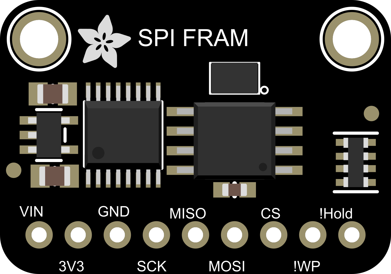
The Adafruit SPI FRAM is a non-volatile memory module that utilizes ferroelectric random access memory (FRAM) technology. This component is designed for applications requiring high-speed data writing, low power consumption, and the ability to retain data without power. It is ideal for use in data logging, real-time clocks, and other scenarios where data must be preserved across power cycles.

Explore Projects Built with Adafruit SPI FRAM

Use Cirkit Designer to design, explore, and prototype these projects online. Some projects support real-time simulation. Click "Open Project" to start designing instantly!
Arduino UNO and ILI9341 Mandelbrot Fractal Display
Image of ILI9341 Sim Test - mandelbrot: A project utilizing Adafruit SPI FRAM in a practical application
This circuit connects an Arduino UNO to an ILI9341 TFT display using SPI communication. The Arduino runs a program to generate and display Mandelbrot fractals on the TFT screen.
Cirkit Designer LogoOpen Project in Cirkit Designer
Raspberry Pi 4B-based RFID Attendance System with OLED Display
Image of Attendence System with RFID : A project utilizing Adafruit SPI FRAM in a practical application
This circuit integrates a Raspberry Pi 4B with an RFID-RC522 module, an ADS1115 ADC, and a 0.96" OLED display. The Raspberry Pi manages SPI communication with the RFID module, I2C communication with the ADC and OLED display, and provides power to the peripherals. The circuit is designed for RFID reading, analog signal digitization, and data display, but requires external software for operation.
Cirkit Designer LogoOpen Project in Cirkit Designer
Arduino Nano Wireless Communication System with nRF24L01 Module
Image of drone reciever: A project utilizing Adafruit SPI FRAM in a practical application
This circuit connects an nRF24L01 wireless transceiver module to an Arduino Nano microcontroller through an adapter board. The Arduino Nano is configured to communicate with the nRF24L01 via SPI (Serial Peripheral Interface), using pins D9 and D10 for chip enable (CE) and chip select (CSN), and pins D11 to D13 for the SPI bus (MOSI, MISO, SCK). An electrolytic capacitor is connected across the power supply lines likely for power stabilization.
Cirkit Designer LogoOpen Project in Cirkit Designer
ESP32-Based RFID Reader with OLED Display
Image of RFID_OLED_ESP32: A project utilizing Adafruit SPI FRAM in a practical application
This circuit features an ESP32 microcontroller connected to an RFID-RC522 module and an OLED display. The ESP32 communicates with the RFID reader via SPI (using pins D23, D22, D18, and D5 for MOSI, MISO, SCK, and SDA respectively) and with the OLED display through I2C (using pins D4 and D15 for SCL and SDA). All devices share a common ground and are powered by the ESP32's 3.3V output, indicating the circuit is likely used for RFID tag reading and data display on the OLED.
Cirkit Designer LogoOpen Project in Cirkit Designer

Explore Projects Built with Adafruit SPI FRAM

Use Cirkit Designer to design, explore, and prototype these projects online. Some projects support real-time simulation. Click "Open Project" to start designing instantly!
Image of ILI9341 Sim Test - mandelbrot: A project utilizing Adafruit SPI FRAM in a practical application
Arduino UNO and ILI9341 Mandelbrot Fractal Display
This circuit connects an Arduino UNO to an ILI9341 TFT display using SPI communication. The Arduino runs a program to generate and display Mandelbrot fractals on the TFT screen.
Cirkit Designer LogoOpen Project in Cirkit Designer
Image of Attendence System with RFID : A project utilizing Adafruit SPI FRAM in a practical application
Raspberry Pi 4B-based RFID Attendance System with OLED Display
This circuit integrates a Raspberry Pi 4B with an RFID-RC522 module, an ADS1115 ADC, and a 0.96" OLED display. The Raspberry Pi manages SPI communication with the RFID module, I2C communication with the ADC and OLED display, and provides power to the peripherals. The circuit is designed for RFID reading, analog signal digitization, and data display, but requires external software for operation.
Cirkit Designer LogoOpen Project in Cirkit Designer
Image of drone reciever: A project utilizing Adafruit SPI FRAM in a practical application
Arduino Nano Wireless Communication System with nRF24L01 Module
This circuit connects an nRF24L01 wireless transceiver module to an Arduino Nano microcontroller through an adapter board. The Arduino Nano is configured to communicate with the nRF24L01 via SPI (Serial Peripheral Interface), using pins D9 and D10 for chip enable (CE) and chip select (CSN), and pins D11 to D13 for the SPI bus (MOSI, MISO, SCK). An electrolytic capacitor is connected across the power supply lines likely for power stabilization.
Cirkit Designer LogoOpen Project in Cirkit Designer
Image of RFID_OLED_ESP32: A project utilizing Adafruit SPI FRAM in a practical application
ESP32-Based RFID Reader with OLED Display
This circuit features an ESP32 microcontroller connected to an RFID-RC522 module and an OLED display. The ESP32 communicates with the RFID reader via SPI (using pins D23, D22, D18, and D5 for MOSI, MISO, SCK, and SDA respectively) and with the OLED display through I2C (using pins D4 and D15 for SCL and SDA). All devices share a common ground and are powered by the ESP32's 3.3V output, indicating the circuit is likely used for RFID tag reading and data display on the OLED.
Cirkit Designer LogoOpen Project in Cirkit Designer

Common Applications and Use Cases

  • Data logging systems
  • Real-time clocks
  • Industrial control systems
  • Gaming and entertainment devices
  • Wearable electronics

Technical Specifications

Key Technical Details

  • Voltage Supply: 3.3V to 5V
  • Operating Current: 10 mA (typical)
  • Memory Size: Varies by model (e.g., 32Kbit, 64Kbit)
  • Interface: SPI (Serial Peripheral Interface)
  • Data Retention: 10+ years
  • Write Endurance: 10^14 write cycles

Pin Configuration and Descriptions

Pin Number Name Description
1 CS Chip Select, active low
2 MISO Master In Slave Out, SPI data output
3 WP Write Protect, active low
4 VSS Ground
5 MOSI Master Out Slave In, SPI data input
6 SCK Serial Clock, SPI clock input
7 HOLD Suspends serial communication without resetting the serial sequence
8 VCC Supply Voltage

Usage Instructions

How to Use the Component in a Circuit

  1. Power Supply: Connect VCC to a 3.3V or 5V power supply and VSS to ground.
  2. SPI Interface: Connect MOSI, MISO, and SCK to the corresponding SPI pins on your microcontroller.
  3. Chip Select: Connect the CS pin to a digital pin on your microcontroller for SPI communication.
  4. Write Protect and Hold: Connect WP and HOLD to VCC if not used, or to a digital pin if control over these functions is required.

Important Considerations and Best Practices

  • Ensure that the power supply is within the specified voltage range.
  • Use pull-up resistors on the CS, WP, and HOLD pins if they are not actively driven by the microcontroller.
  • Avoid exposing the chip to temperatures outside the specified operating range.
  • When integrating with a microcontroller, ensure that the SPI clock speed does not exceed the maximum frequency specified for the FRAM chip.

Example Code for Arduino UNO

#include <SPI.h>
#include <Adafruit_FRAM_SPI.h>

// Pin definitions
#define CS_PIN 10

// Create an FRAM_SPI instance
Adafruit_FRAM_SPI fram = Adafruit_FRAM_SPI(CS_PIN);

void setup() {
  Serial.begin(9600);
  // Initialize SPI
  SPI.begin();
  
  // Initialize the FRAM module
  if (fram.begin()) {
    Serial.println("Found SPI FRAM");
  } else {
    Serial.println("No SPI FRAM found ... check your connections");
  }
  
  // Write data to FRAM
  uint8_t dataToWrite = 42; // Example data
  fram.writeEnable(true);
  fram.write8(0, dataToWrite);
  fram.writeEnable(false);
  
  // Read data from FRAM
  uint8_t readData = fram.read8(0);
  Serial.print("Data read from FRAM: ");
  Serial.println(readData);
}

void loop() {
  // Code to interact with FRAM can be placed here
}

Troubleshooting and FAQs

Common Issues

  • FRAM not detected: Ensure all connections are secure and the correct CS pin is defined in your code.
  • Incorrect data read/write: Verify that the SPI clock speed is within the FRAM's operating range and that the power supply is stable.
  • Write operations not persisting: Make sure the write protect (WP) pin is not active or incorrectly wired.

Solutions and Tips for Troubleshooting

  • Double-check wiring against the pin configuration table.
  • Use serial output to debug and verify that initialization is successful.
  • Ensure that the library used is up-to-date and compatible with your FRAM model.

FAQs

Q: How long will the FRAM retain data? A: The FRAM is rated to retain data for over 10 years without power.

Q: Can I use the Adafruit SPI FRAM with a 5V microcontroller? A: Yes, the Adafruit SPI FRAM can operate with a supply voltage of up to 5V.

Q: How many write cycles can the FRAM handle? A: The FRAM can handle up to 10^14 write cycles, making it highly durable for write-intensive applications.

Q: Is it necessary to use the HOLD pin? A: The HOLD pin is optional and is used to pause communication without resetting the SPI connection. If not used, it should be tied to VCC.