How to Use Heart Sensor and SpO2: Examples, Pinouts, and Specs
Introduction
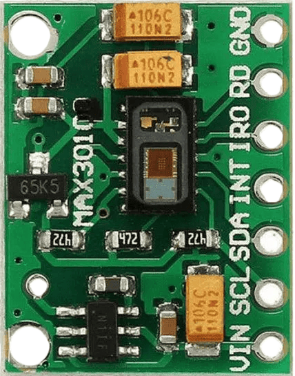
The Heart Sensor and SpO2 module is a compact and versatile device designed to measure heart rate and blood oxygen saturation (SpO2) levels. It uses photoplethysmography (PPG) technology, which detects changes in blood volume by shining light through the skin and measuring the reflected or transmitted light. This module is widely used in health monitoring systems, fitness trackers, and medical devices.
Explore Projects Built with Heart Sensor and SpO2
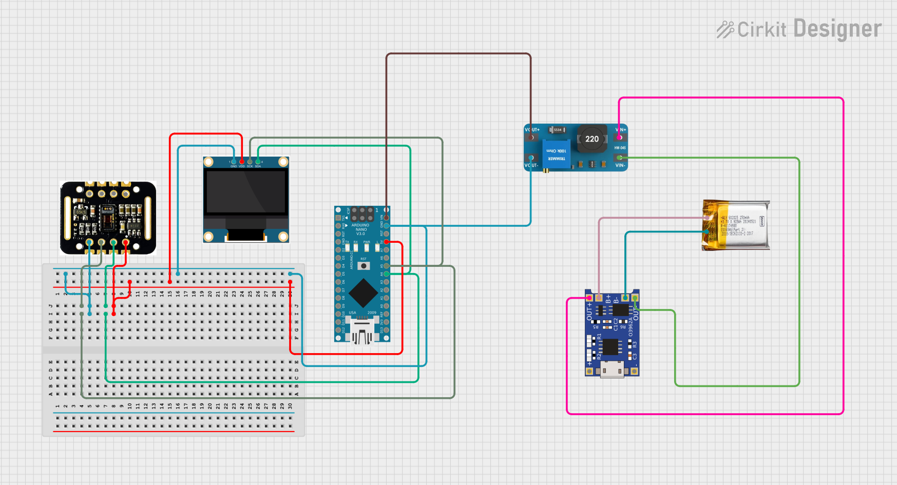
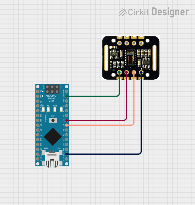

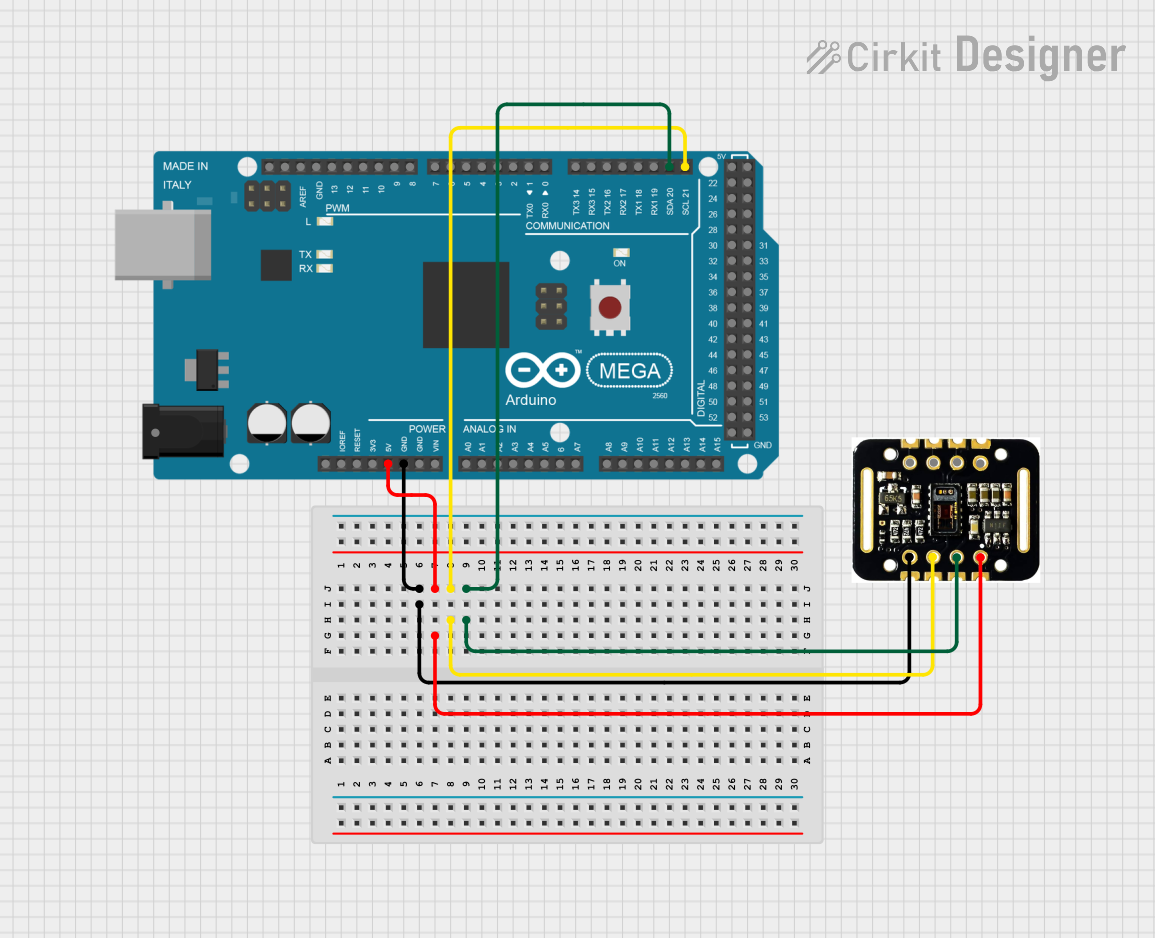
Explore Projects Built with Heart Sensor and SpO2
Common Applications
- Wearable health monitoring devices
- Fitness trackers
- Medical diagnostics
- IoT-based health monitoring systems
- Research and development in biomedical engineering
Technical Specifications
The Heart Sensor and SpO2 module typically includes an integrated optical sensor, LEDs, and a photodetector. Below are the key technical details:
General Specifications
| Parameter | Value |
|---|---|
| Operating Voltage | 1.8V to 3.3V |
| Operating Current | 5mA to 10mA |
| Measurement Range | Heart Rate: 30-240 BPM |
| SpO2: 70% to 100% | |
| Communication Protocol | I2C |
| Sampling Rate | Configurable (e.g., 50Hz-100Hz) |
| Dimensions | ~12mm x 10mm x 3mm |
Pin Configuration
| Pin Name | Pin Number | Description |
|---|---|---|
| VCC | 1 | Power supply input (1.8V to 3.3V) |
| GND | 2 | Ground |
| SDA | 3 | I2C data line |
| SCL | 4 | I2C clock line |
| INT | 5 | Interrupt pin for data-ready signaling |
Usage Instructions
How to Use the Component in a Circuit
- Power Supply: Connect the VCC pin to a 3.3V power source and the GND pin to ground.
- I2C Communication: Connect the SDA and SCL pins to the corresponding I2C pins on your microcontroller (e.g., Arduino UNO: A4 for SDA, A5 for SCL).
- Interrupt Pin: Optionally, connect the INT pin to a GPIO pin on your microcontroller to detect when new data is available.
- Pull-Up Resistors: Ensure that the I2C lines (SDA and SCL) have pull-up resistors (typically 4.7kΩ) if not already included on the module.
Important Considerations
- Ambient Light Interference: Avoid exposing the sensor to direct sunlight or strong ambient light, as this can affect accuracy.
- Skin Contact: Ensure proper contact with the skin for accurate readings. The sensor should be placed on a fingertip or earlobe.
- Sampling Rate: Configure the sampling rate based on your application requirements. Higher rates may consume more power.
- Calibration: Some modules may require calibration for optimal performance. Refer to the manufacturer's datasheet for details.
Example Code for Arduino UNO
Below is an example code to interface the Heart Sensor and SpO2 module with an Arduino UNO using the I2C protocol:
#include <Wire.h>

// Define I2C address of the sensor
#define SENSOR_ADDRESS 0x57

void setup() {
  Wire.begin(); // Initialize I2C communication
  Serial.begin(9600); // Initialize serial communication for debugging

  // Initialize the sensor
  if (!initializeSensor()) {
    Serial.println("Sensor initialization failed!");
    while (1); // Halt execution if initialization fails
  }
  Serial.println("Sensor initialized successfully.");
}

void loop() {
  // Read heart rate and SpO2 data
  int heartRate = readHeartRate();
  int spo2 = readSpO2();

  // Print the data to the serial monitor
  Serial.print("Heart Rate: ");
  Serial.print(heartRate);
  Serial.print(" BPM, SpO2: ");
  Serial.print(spo2);
  Serial.println(" %");

  delay(1000); // Wait for 1 second before the next reading
}

bool initializeSensor() {
  Wire.beginTransmission(SENSOR_ADDRESS);
  // Send initialization commands to the sensor
  Wire.write(0x01); // Example command to initialize the sensor
  return (Wire.endTransmission() == 0); // Check if the transmission was successful
}

int readHeartRate() {
  Wire.beginTransmission(SENSOR_ADDRESS);
  Wire.write(0x02); // Command to request heart rate data
  Wire.endTransmission();

  Wire.requestFrom(SENSOR_ADDRESS, 1); // Request 1 byte of data
  if (Wire.available()) {
    return Wire.read(); // Return the heart rate value
  }
  return -1; // Return -1 if no data is available
}

int readSpO2() {
  Wire.beginTransmission(SENSOR_ADDRESS);
  Wire.write(0x03); // Command to request SpO2 data
  Wire.endTransmission();

  Wire.requestFrom(SENSOR_ADDRESS, 1); // Request 1 byte of data
  if (Wire.available()) {
    return Wire.read(); // Return the SpO2 value
  }
  return -1; // Return -1 if no data is available
}
Notes on the Code
- Replace
0x57with the actual I2C address of your sensor if it differs. - The initialization and data-reading commands (
0x01,0x02,0x03) are placeholders. Refer to the sensor's datasheet for the correct commands.
Troubleshooting and FAQs
Common Issues
No Data Output:
- Ensure the sensor is properly powered and connected to the microcontroller.
- Verify the I2C address and commands used in the code.
- Check for loose or faulty wiring.
Inaccurate Readings:
- Ensure the sensor is in proper contact with the skin.
- Avoid strong ambient light or electrical noise near the sensor.
- Verify that the sampling rate and configuration match the application requirements.
I2C Communication Errors:
- Check if pull-up resistors are present on the SDA and SCL lines.
- Ensure the I2C clock speed is compatible with the sensor (typically 100kHz or 400kHz).
FAQs
Q: Can this sensor be used with a 5V microcontroller?
A: Most Heart Sensor and SpO2 modules operate at 3.3V. Use a level shifter to interface with 5V microcontrollers.
Q: How do I improve measurement accuracy?
A: Ensure proper skin contact, minimize motion artifacts, and avoid ambient light interference.
Q: Can I use this sensor for continuous monitoring?
A: Yes, but ensure adequate power supply and proper thermal management to prevent overheating.
Q: What is the typical lifespan of the sensor?
A: The lifespan depends on usage and environmental conditions but is typically several years under normal operation.