How to Use SMPS : Examples, Pinouts, and Specs
Introduction
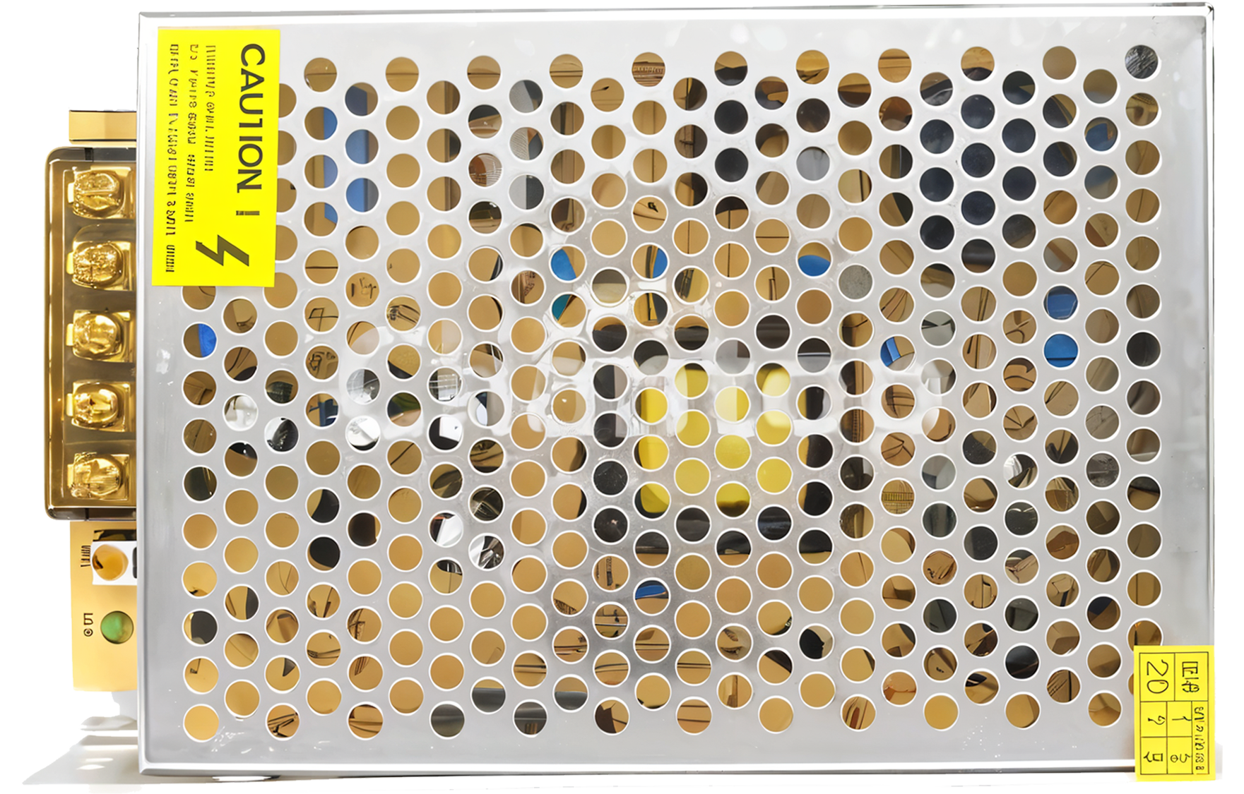
The Switched-Mode Power Supply (SMPS) is an electronic power supply that incorporates a switching regulator to convert electrical power efficiently. Unlike traditional linear power supplies, SMPS uses a high-frequency switching element to regulate the output voltage, resulting in higher efficiency and reduced heat dissipation. This makes SMPS ideal for applications where energy efficiency and compact size are critical.
Explore Projects Built with SMPS


Explore Projects Built with SMPS
Common Applications and Use Cases
- Computers and Servers: SMPS is widely used in computer power supplies due to its high efficiency and ability to handle varying loads.
- Telecommunications: Used in base stations and other telecom equipment to ensure stable power supply.
- Consumer Electronics: Found in devices like televisions, gaming consoles, and home audio systems.
- Industrial Equipment: Used in machinery and control systems for reliable power conversion.
- Battery Chargers: Efficiently converts AC to DC for charging batteries in various devices.
Technical Specifications
Key Technical Details
| Parameter | Value |
|---|---|
| Input Voltage | 90-264V AC |
| Output Voltage | 5V, 12V, 24V DC (varies by model) |
| Output Current | 0.5A to 20A (varies by model) |
| Efficiency | Up to 95% |
| Switching Frequency | 20kHz to 1MHz |
| Operating Temperature | -20°C to 70°C |
| Protection Features | Over-voltage, Over-current, Short-circuit |
Pin Configuration and Descriptions
| Pin Number | Pin Name | Description |
|---|---|---|
| 1 | AC_L | AC Line Input |
| 2 | AC_N | AC Neutral Input |
| 3 | GND | Ground |
| 4 | Vout+ | Positive DC Output |
| 5 | Vout- | Negative DC Output |
| 6 | Remote On/Off | Remote Control for On/Off Switching |
| 7 | PG (Power Good) | Power Good Signal |
Usage Instructions
How to Use the Component in a Circuit
Connect the AC Input:
- Connect the AC_L pin to the live wire of the AC supply.
- Connect the AC_N pin to the neutral wire of the AC supply.
Connect the DC Output:
- Connect the Vout+ pin to the positive terminal of your load.
- Connect the Vout- pin to the negative terminal of your load.
Grounding:
- Ensure the GND pin is connected to the ground of your circuit to avoid any potential differences.
Remote On/Off Control:
- Use the Remote On/Off pin to control the power supply remotely. This can be connected to a microcontroller or a manual switch.
Power Good Signal:
- The PG pin can be used to monitor the status of the power supply. It will indicate whether the output voltage is within the specified range.
Important Considerations and Best Practices
- Heat Dissipation: Ensure adequate ventilation or cooling to prevent overheating.
- Load Regulation: Verify that the load connected to the SMPS is within the specified current range.
- Safety Precautions: Always handle the AC input with care to avoid electric shock.
- EMI Considerations: Use proper filtering techniques to minimize electromagnetic interference.
Troubleshooting and FAQs
Common Issues Users Might Face
No Output Voltage:
- Solution: Check the AC input connections and ensure the power supply is receiving power. Verify that the Remote On/Off pin is correctly configured.
Overheating:
- Solution: Ensure proper ventilation and check if the load exceeds the specified current rating.
Output Voltage Fluctuations:
- Solution: Verify the load stability and check for any loose connections. Ensure the input voltage is within the specified range.
Power Good Signal Not Active:
- Solution: Check the output voltage and ensure it is within the specified range. Verify the connections to the PG pin.
Solutions and Tips for Troubleshooting
- Use a Multimeter: To check the input and output voltages.
- Check Connections: Ensure all connections are secure and correctly configured.
- Consult the Datasheet: Refer to the manufacturer's datasheet for detailed specifications and troubleshooting tips.
Example Code for Arduino UNO
If you are using the SMPS with an Arduino UNO to control the Remote On/Off functionality, you can use the following example code:
// Define the pin connected to the Remote On/Off of the SMPS
const int remotePin = 7;

void setup() {
  // Initialize the remotePin as an output
  pinMode(remotePin, OUTPUT);

  // Turn on the SMPS
  digitalWrite(remotePin, HIGH);
}

void loop() {
  // Example: Toggle the SMPS on and off every 5 seconds

  // Turn off the SMPS
  digitalWrite(remotePin, LOW);
  delay(5000); // Wait for 5 seconds

  // Turn on the SMPS
  digitalWrite(remotePin, HIGH);
  delay(5000); // Wait for 5 seconds
}
This code initializes the remote control pin as an output and toggles the SMPS on and off every 5 seconds. Adjust the pin number and delay times as needed for your specific application.
This documentation provides a comprehensive overview of the Switched-Mode Power Supply (SMPS), including its technical specifications, usage instructions, and troubleshooting tips. Whether you are a beginner or an experienced user, this guide will help you effectively utilize the SMPS in your projects.