
How to Use Adafruit Feather nRF52840: Examples, Pinouts, and Specs
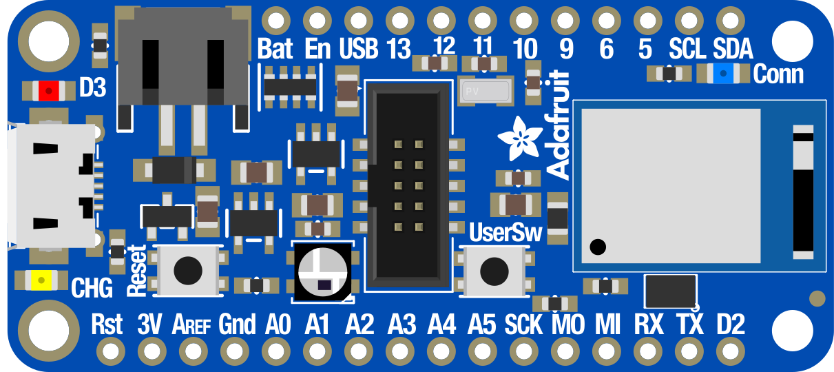
 Design with Adafruit Feather nRF52840 in Cirkit Designer
Introduction
The Adafruit Feather nRF52840 (Manufacturer Part ID: 4062) is a compact and versatile microcontroller board built around the Nordic Semiconductor nRF52840 chip. This board is designed for Internet of Things (IoT) applications and supports multiple wireless communication protocols, including Bluetooth Low Energy (BLE), Thread, and Zigbee. It features built-in USB support, battery charging capabilities, and a wide range of GPIO pins for interfacing with sensors, actuators, and other peripherals.
Explore Projects Built with Adafruit Feather nRF52840
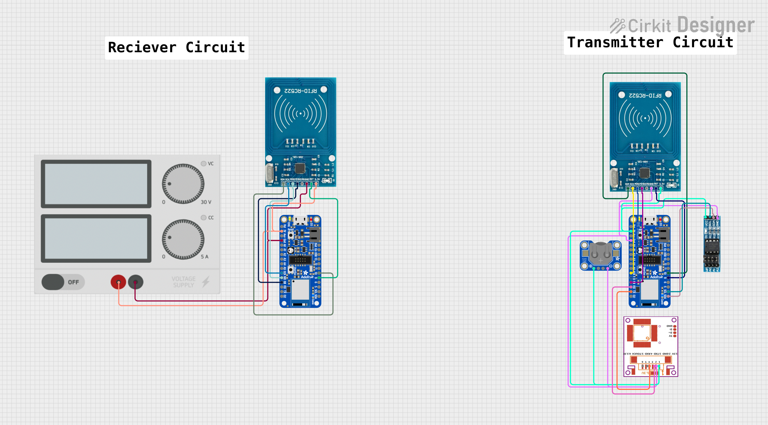 Open Project in Cirkit Designer
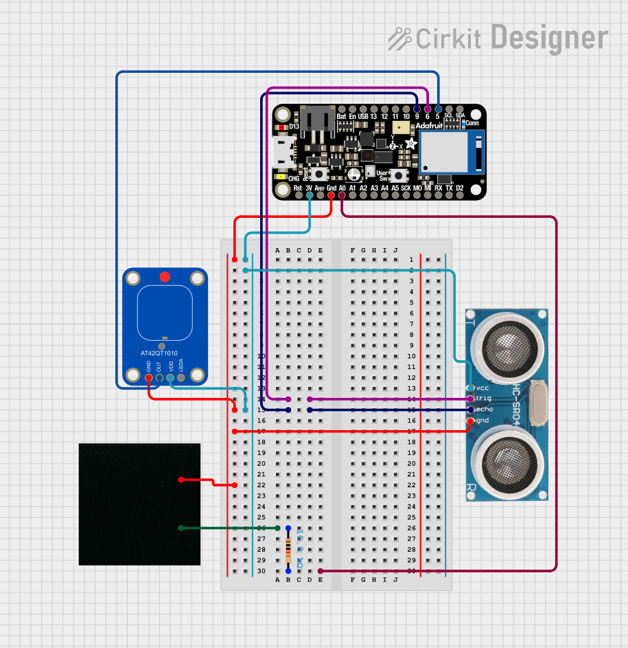 Open Project in Cirkit Designer
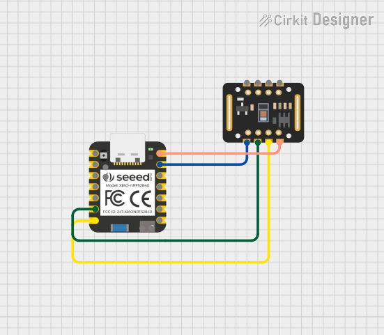 Open Project in Cirkit Designer
 Open Project in Cirkit Designer
Explore Projects Built with Adafruit Feather nRF52840
Open Project in Cirkit DesignerOpen Project in Cirkit DesignerOpen Project in Cirkit DesignerOpen Project in Cirkit DesignerCommon Applications
- IoT devices and smart home applications
- Wearable technology
- Wireless sensor networks
- Bluetooth-enabled projects
- Prototyping with Thread or Zigbee protocols
- Low-power, battery-operated devices
Technical Specifications
The following table outlines the key technical details of the Adafruit Feather nRF52840:
| Specification | Details |
|---|---|
| Microcontroller | Nordic nRF52840 (ARM Cortex-M4F @ 64 MHz) |
| Flash Memory | 1 MB |
| RAM | 256 KB |
| Wireless Protocols | Bluetooth Low Energy (BLE), Thread, Zigbee |
| Operating Voltage | 3.3V |
| Input Voltage | 3.3V to 6V (via USB or LiPo battery) |
| Battery Support | 3.7V LiPo battery with built-in charging circuit |
| GPIO Pins | 21 GPIO pins (including analog and digital pins) |
| Analog Inputs | 8 ADC channels (12-bit resolution) |
| PWM Outputs | 4 PWM channels |
| Communication Interfaces | UART, I2C, SPI |
| USB Support | Native USB with USB-C connector |
| Dimensions | 51mm x 23mm x 8mm |
| Weight | 5.7g |
Pin Configuration
The Adafruit Feather nRF52840 features a variety of pins for interfacing with external components. Below is a summary of the pin configuration:
| Pin | Function | Description |
|---|---|---|
| VIN | Power Input | Accepts 3.3V to 6V input from USB or battery. |
| GND | Ground | Common ground for the circuit. |
| 3.3V | Power Output | Regulated 3.3V output for powering external components. |
| A0–A7 | Analog Inputs | 12-bit ADC channels for reading analog signals. |
| D0–D13 | Digital I/O | General-purpose digital input/output pins. |
| SDA | I2C Data Line | Used for I2C communication. |
| SCL | I2C Clock Line | Used for I2C communication. |
| MOSI | SPI Master Out, Slave In | SPI data output. |
| MISO | SPI Master In, Slave Out | SPI data input. |
| SCK | SPI Clock | SPI clock signal. |
| RX | UART Receive | Serial data input for UART communication. |
| TX | UART Transmit | Serial data output for UART communication. |
| EN | Enable | Enables or disables the 3.3V regulator. |
| BAT | Battery Voltage | Direct connection to the LiPo battery. |
| USB | USB Power | Power input from USB-C connector. |
Usage Instructions
Using the Adafruit Feather nRF52840 in a Circuit
Powering the Board:
- Connect a 3.7V LiPo battery to the JST connector, or
- Power the board via the USB-C connector using a 5V USB power source.
- The onboard regulator will provide a stable 3.3V to the microcontroller and peripherals.
Programming the Board:
- Install the Arduino IDE and the Adafruit nRF52 Board Support Package.
- Connect the board to your computer using a USB-C cable.
- Select the correct board and port in the Arduino IDE:
- Go to
Tools > Board > Adafruit Feather nRF52840. - Go to
Tools > Portand select the appropriate COM port.
- Go to
- Write or upload your code to the board.
Connecting Peripherals:
- Use the GPIO pins to connect sensors, actuators, or other devices.
- For analog sensors, connect them to the A0–A7 pins.
- For I2C devices, connect them to the SDA and SCL pins.
- For SPI devices, use the MOSI, MISO, and SCK pins.
Wireless Communication:
- Use the built-in BLE, Thread, or Zigbee capabilities for wireless communication.
- Libraries such as Adafruit Bluefruit can simplify BLE programming.
Example Code: Blink an LED
The following example demonstrates how to blink an LED connected to pin D13:
// Blink an LED connected to pin D13 on the Adafruit Feather nRF52840

void setup() {
  pinMode(13, OUTPUT); // Set pin D13 as an output
}

void loop() {
  digitalWrite(13, HIGH); // Turn the LED on
  delay(1000);            // Wait for 1 second
  digitalWrite(13, LOW);  // Turn the LED off
  delay(1000);            // Wait for 1 second
}
Important Considerations
- Voltage Levels: Ensure that all connected peripherals operate at 3.3V logic levels to avoid damaging the board.
- Battery Charging: If using a LiPo battery, the onboard charging circuit will automatically charge the battery when connected to USB power.
- Heat Management: Avoid prolonged high-current operations to prevent overheating.
Troubleshooting and FAQs
Common Issues
Board Not Detected by Computer:
- Ensure the USB-C cable is a data cable (not just a charging cable).
- Check that the correct COM port is selected in the Arduino IDE.
- Try pressing the reset button twice to enter bootloader mode.
Code Upload Fails:
- Verify that the correct board and port are selected in the Arduino IDE.
- Ensure the Adafruit nRF52 Board Support Package is installed.
Wireless Communication Not Working:
- Check that the BLE or Zigbee library is correctly installed and configured.
- Ensure the device is within range of the wireless receiver.
Tips for Troubleshooting
- Use the Serial Monitor in the Arduino IDE to debug your code.
- Check the onboard LED indicators for power and activity status.
- Refer to the Adafruit Feather nRF52840 product page for additional resources and support.
FAQs
Q: Can I power the board with a 5V power supply?
A: Yes, you can power the board via the USB-C connector or the VIN pin with a 5V power supply.
Q: Does the board support external antennas?
A: No, the Adafruit Feather nRF52840 uses an onboard PCB antenna for wireless communication.
Q: Can I use this board with CircuitPython?
A: Yes, the Adafruit Feather nRF52840 is compatible with CircuitPython. You can install CircuitPython firmware and use Python scripts to program the board.
Q: What is the maximum range for BLE communication?
A: The BLE range depends on environmental factors but typically extends up to 30 meters in open spaces.