How to Use HDMI Breakout Board: Examples, Pinouts, and Specs
Introduction
The HDMI Breakout Board is a compact circuit board designed to provide access to the individual pins of an HDMI connector. This component simplifies the process of connecting, testing, and prototyping HDMI signals by breaking out the HDMI pins into easily accessible solder pads or headers. It is an essential tool for developers working on HDMI-based projects, enabling quick and reliable connections without the need for custom HDMI cables or connectors.
Explore Projects Built with HDMI Breakout Board


Explore Projects Built with HDMI Breakout Board
Common Applications and Use Cases
- Prototyping HDMI-based devices such as displays, media players, and signal processors.
- Debugging and testing HDMI signals in hardware development.
- Educational purposes for learning about HDMI signal structure and pinouts.
- Interfacing HDMI devices with microcontrollers or FPGA boards for custom projects.
Technical Specifications
The HDMI Breakout Board is designed to comply with the HDMI standard and provides access to all 19 pins of a standard HDMI Type-A connector. Below are the key technical details:
Key Specifications
- Connector Type: HDMI Type-A (19 pins)
- Voltage Rating: 5V (HDMI standard)
- Signal Compatibility: TMDS (Transition-Minimized Differential Signaling)
- Board Dimensions: Typically 25mm x 30mm (varies by manufacturer)
- Pin Access: Solder pads or 2.54mm (0.1-inch) header pins
- Supported HDMI Versions: Up to HDMI 2.0 (depending on the breakout board design)
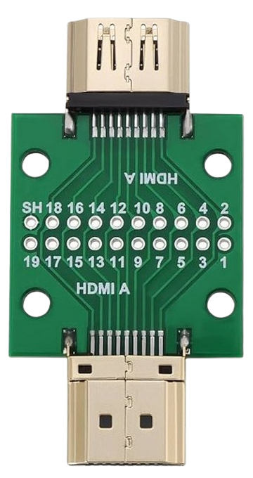
Pin Configuration and Descriptions
The HDMI Breakout Board provides access to the following pins:
| Pin Number | Pin Name | Description |
|---|---|---|
| 1 | TMDS Data2+ | Positive differential signal for TMDS channel 2 |
| 2 | TMDS Data2 Shield | Shield for TMDS channel 2 |
| 3 | TMDS Data2- | Negative differential signal for TMDS channel 2 |
| 4 | TMDS Data1+ | Positive differential signal for TMDS channel 1 |
| 5 | TMDS Data1 Shield | Shield for TMDS channel 1 |
| 6 | TMDS Data1- | Negative differential signal for TMDS channel 1 |
| 7 | TMDS Data0+ | Positive differential signal for TMDS channel 0 |
| 8 | TMDS Data0 Shield | Shield for TMDS channel 0 |
| 9 | TMDS Data0- | Negative differential signal for TMDS channel 0 |
| 10 | TMDS Clock+ | Positive differential signal for TMDS clock |
| 11 | TMDS Clock Shield | Shield for TMDS clock |
| 12 | TMDS Clock- | Negative differential signal for TMDS clock |
| 13 | CEC | Consumer Electronics Control signal |
| 14 | Reserved (N.C.) | Reserved, not connected |
| 15 | SCL | I2C clock for DDC (Display Data Channel) |
| 16 | SDA | I2C data for DDC |
| 17 | DDC/CEC Ground | Ground for DDC and CEC |
| 18 | +5V Power | 5V power supply from the HDMI source |
| 19 | Hot Plug Detect | Signal to indicate the presence of an HDMI device |
Usage Instructions
How to Use the HDMI Breakout Board in a Circuit
- Connect the HDMI Source and Sink: Plug the HDMI cable from the source device (e.g., a computer or media player) into the HDMI connector on the breakout board. Connect the breakout board to the sink device (e.g., a display or monitor) using jumper wires or soldered connections.
- Access Individual Pins: Use the labeled solder pads or header pins to access specific HDMI signals. For example, you can connect the TMDS data lines to an oscilloscope for signal analysis or to an FPGA for processing.
- Power the Board: Ensure the +5V pin is connected to a stable 5V power source. This is typically provided by the HDMI source device.
- Monitor Signals: Use test equipment such as logic analyzers or oscilloscopes to monitor and debug HDMI signals as needed.
Important Considerations and Best Practices
- Signal Integrity: HDMI signals operate at high frequencies, so ensure short and properly shielded connections to minimize noise and signal degradation.
- Grounding: Always connect the ground pins (e.g., DDC/CEC Ground) to a common ground to avoid ground loops and ensure proper signal reference.
- Avoid Overloading: Do not draw excessive current from the +5V pin, as it is typically limited to 50mA by the HDMI source device.
- Static Protection: Handle the breakout board with care to avoid electrostatic discharge (ESD) damage to the sensitive HDMI pins.
Example: Interfacing with an Arduino UNO
The HDMI Breakout Board can be used to read the Hot Plug Detect (HPD) signal or communicate with the DDC (I2C) lines. Below is an example Arduino sketch to read the HPD signal:
// Define the pin connected to the Hot Plug Detect (HPD) signal
const int hpdPin = 2;

void setup() {
  // Initialize the serial monitor for debugging
  Serial.begin(9600);

  // Set the HPD pin as an input
  pinMode(hpdPin, INPUT);
}

void loop() {
  // Read the state of the HPD signal
  int hpdState = digitalRead(hpdPin);

  // Print the HPD state to the serial monitor
  if (hpdState == HIGH) {
    Serial.println("HDMI device detected!");
  } else {
    Serial.println("No HDMI device detected.");
  }

  // Wait for 1 second before checking again
  delay(1000);
}
Troubleshooting and FAQs
Common Issues and Solutions
No Signal Detected on the HDMI Sink
- Cause: Loose or incorrect connections.
- Solution: Verify that all HDMI pins are properly connected and that the HDMI cable is securely plugged in.
Interference or Noise in Signals
- Cause: Long or unshielded wires.
- Solution: Use short, shielded wires for high-frequency signals like TMDS lines.
Hot Plug Detect (HPD) Signal Not Working
- Cause: HPD pin not connected or incorrect voltage level.
- Solution: Ensure the HPD pin is connected to the correct input pin on your microcontroller or test equipment.
I2C Communication Fails
- Cause: Incorrect pull-up resistors on the SDA and SCL lines.
- Solution: Add 4.7kΩ pull-up resistors to the SDA and SCL lines if not already present.
FAQs
Q: Can the HDMI Breakout Board handle 4K signals?
A: Yes, as long as the breakout board and connected devices support HDMI 2.0 or higher.Q: Is the breakout board compatible with microcontrollers?
A: Yes, it can be used with microcontrollers like Arduino or Raspberry Pi to interface with HDMI signals such as HPD, CEC, or DDC.Q: Do I need external power for the breakout board?
A: No, the +5V power is typically supplied by the HDMI source device. However, ensure the source device can provide sufficient current.