How to Use Buck-Boost Converter 12V: Examples, Pinouts, and Specs
Introduction
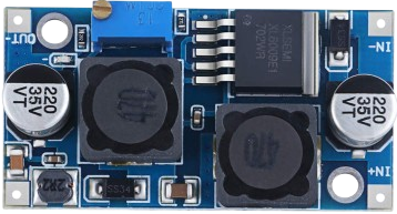
A Buck-Boost Converter is a type of DC-DC converter that can step up (boost) or step down (buck) an input voltage to a desired output voltage level. This makes it ideal for applications where the input voltage may vary above or below the desired output voltage. The 12V Buck-Boost Converter is specifically designed to regulate voltage to 12V, ensuring stable power delivery in a wide range of scenarios.
Explore Projects Built with Buck-Boost Converter 12V


Explore Projects Built with Buck-Boost Converter 12V
Common Applications and Use Cases
- Battery-powered devices where the input voltage fluctuates (e.g., lithium-ion batteries)
- Automotive electronics to stabilize voltage for 12V systems
- Renewable energy systems, such as solar panels
- Portable devices requiring consistent voltage output
- Embedded systems and microcontroller-based projects
Technical Specifications
Below are the key technical details for the 12V Buck-Boost Converter:
| Parameter | Value |
|---|---|
| Input Voltage Range | 5V to 32V |
| Output Voltage | 12V (adjustable in some models) |
| Output Current | Up to 3A (varies by model) |
| Efficiency | Up to 95% |
| Switching Frequency | 150 kHz to 300 kHz |
| Operating Temperature | -40°C to +85°C |
| Dimensions | Typically 45mm x 20mm x 14mm |
Pin Configuration and Descriptions
The Buck-Boost Converter typically has the following pin configuration:
| Pin Name | Description |
|---|---|
| VIN | Input voltage pin (connect to power source) |
| GND | Ground pin (common ground for input and output) |
| VOUT | Output voltage pin (connect to load) |
| EN (optional) | Enable pin (used to turn the converter on/off) |
| ADJ (optional) | Adjustment pin (for fine-tuning output voltage) |
Usage Instructions
How to Use the Buck-Boost Converter in a Circuit
Connect the Input Voltage:
- Connect the VIN pin to the positive terminal of your power source.
- Connect the GND pin to the negative terminal of your power source.
Connect the Output Voltage:
- Connect the VOUT pin to the positive terminal of your load.
- Ensure the load's ground is connected to the GND pin.
Enable the Converter (if applicable):
- If the converter has an EN (Enable) pin, connect it to a HIGH signal (e.g., 5V) to activate the converter. Leave it unconnected or LOW to disable it.
Adjust the Output Voltage (if applicable):
- If the converter has an ADJ pin, use a small screwdriver to turn the potentiometer and fine-tune the output voltage. Use a multimeter to monitor the output voltage during adjustment.
Important Considerations and Best Practices
- Input Voltage Range: Ensure the input voltage is within the specified range (5V to 32V). Exceeding this range may damage the converter.
- Heat Dissipation: For high current loads, the converter may generate heat. Use a heatsink or active cooling if necessary.
- Load Requirements: Verify that the load does not exceed the maximum output current rating of the converter.
- Polarity: Double-check the polarity of all connections to avoid damage to the converter or connected devices.
Example: Using the Buck-Boost Converter with an Arduino UNO
The Buck-Boost Converter can be used to power an Arduino UNO from a variable power source. Below is an example circuit and code:
Circuit Connections
- Connect the VIN pin of the converter to a 9V battery.
- Connect the GND pin of the converter to the battery's negative terminal.
- Connect the VOUT pin of the converter to the Arduino UNO's VIN pin.
- Connect the GND pin of the converter to the Arduino UNO's GND pin.
Arduino Code Example
// Example code to read a sensor and print data to the Serial Monitor
// The Buck-Boost Converter provides a stable 12V to the Arduino UNO

const int sensorPin = A0; // Analog pin connected to the sensor
int sensorValue = 0;      // Variable to store the sensor reading

void setup() {
  Serial.begin(9600); // Initialize serial communication at 9600 baud
}

void loop() {
  sensorValue = analogRead(sensorPin); // Read the sensor value
  Serial.print("Sensor Value: ");
  Serial.println(sensorValue); // Print the sensor value to the Serial Monitor
  delay(1000); // Wait for 1 second before the next reading
}
Troubleshooting and FAQs
Common Issues and Solutions
No Output Voltage:
- Cause: Input voltage is not connected or is outside the specified range.
- Solution: Verify the input voltage and connections. Ensure the EN pin is HIGH (if applicable).
Overheating:
- Cause: Excessive current draw or insufficient cooling.
- Solution: Reduce the load current or add a heatsink to the converter.
Fluctuating Output Voltage:
- Cause: Input voltage is unstable or load exceeds the converter's capacity.
- Solution: Use a stable power source and ensure the load is within the converter's specifications.
Damaged Converter:
- Cause: Reverse polarity or input voltage exceeds the maximum rating.
- Solution: Replace the converter and double-check all connections before powering on.
FAQs
Q: Can I use the Buck-Boost Converter to power a Raspberry Pi?
A: Yes, but ensure the output voltage is set to 5V (if adjustable) and the current rating meets the Raspberry Pi's requirements.
Q: How do I know if the converter is working?
A: Use a multimeter to measure the output voltage. It should match the specified output (e.g., 12V).
Q: Can I use this converter with a solar panel?
A: Yes, as long as the solar panel's output voltage is within the converter's input range (5V to 32V).