Cirkit Designer Logo
Cirkit Designer
Your all-in-one circuit design IDE
Home / 
Component Documentation

How to Use DUOWEISI 12864-889: Examples, Pinouts, and Specs

Image of DUOWEISI 12864-889
Cirkit Designer LogoDesign with DUOWEISI 12864-889 in Cirkit Designer

Introduction

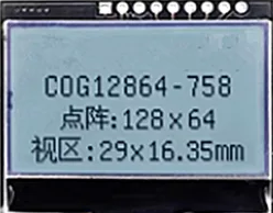
The DUOWEISI 12864-889 is a graphic LCD module manufactured by LCD, featuring a resolution of 128x64 pixels. This module is widely used in embedded systems for displaying text, graphics, and custom images. Its compact size and versatile functionality make it ideal for applications such as industrial control panels, DIY electronics projects, and user interface displays in consumer electronics.

Explore Projects Built with DUOWEISI 12864-889

Use Cirkit Designer to design, explore, and prototype these projects online. Some projects support real-time simulation. Click "Open Project" to start designing instantly!
ESP32-Based Environmental Monitoring and Alert System with Solar Charging
Image of Schematic: A project utilizing DUOWEISI 12864-889 in a practical application
This circuit features an ESP32 Devkit V1 microcontroller connected to various sensors and devices, including a DHT11 temperature and humidity sensor, an MQ-2 gas sensor, and a WS2812 RGB LED strip. The ESP32 controls the LED strip and processes sensor readings, while a SIM900A module provides cellular communication capabilities. Power management is handled by a UPS module fed by a 12V battery charged via a solar panel and charge controller, with voltage regulation provided by step-down converters. Additionally, a piezo buzzer is included for audible alerts, and the system's safety is ensured by a circuit breaker connected to a switching power supply for AC to DC conversion.
Cirkit Designer LogoOpen Project in Cirkit Designer
ESP32 and BW16-Kit-1 Microcontroller Communication Hub with Buzzer Notification
Image of BiJiQ Wi-Fi To.oL: A project utilizing DUOWEISI 12864-889 in a practical application
This circuit features two ESP32 microcontrollers configured to communicate with each other via serial connection, as indicated by the cross-connection of their TX2 and RX2 pins. A BW16-Kit-1 microcontroller is also included, interfacing with one of the ESP32s through pins D26 and D27. Power is supplied to the microcontrollers through a step-down buck converter connected to a 5V Type C DC socket, and a buzzer is driven by one of the ESP32s, potentially for audio signaling purposes.
Cirkit Designer LogoOpen Project in Cirkit Designer
I2C-Controlled OLED Display with External EEPROM and Interactive Pushbuttons
Image of godmode: A project utilizing DUOWEISI 12864-889 in a practical application
This is a microcontroller-based interactive device featuring a Wemos D1 Mini, an OLED display, external EEPROM, and an I/O expander. It includes user input buttons and status LEDs, with potential MIDI interface capabilities.
Cirkit Designer LogoOpen Project in Cirkit Designer
Wi-Fi Controlled RGB LED and OLED Display with ESP8266
Image of ESP thermometer reciever: A project utilizing DUOWEISI 12864-889 in a practical application
This circuit features an ESP8266 microcontroller interfaced with a 128x64 OLED display via I2C for visual output and an RGB LED controlled through current-limiting resistors. The ESP8266 provides power and control signals to both the display and the LED, enabling visual feedback and status indication.
Cirkit Designer LogoOpen Project in Cirkit Designer

Explore Projects Built with DUOWEISI 12864-889

Use Cirkit Designer to design, explore, and prototype these projects online. Some projects support real-time simulation. Click "Open Project" to start designing instantly!
Image of Schematic: A project utilizing DUOWEISI 12864-889 in a practical application
ESP32-Based Environmental Monitoring and Alert System with Solar Charging
This circuit features an ESP32 Devkit V1 microcontroller connected to various sensors and devices, including a DHT11 temperature and humidity sensor, an MQ-2 gas sensor, and a WS2812 RGB LED strip. The ESP32 controls the LED strip and processes sensor readings, while a SIM900A module provides cellular communication capabilities. Power management is handled by a UPS module fed by a 12V battery charged via a solar panel and charge controller, with voltage regulation provided by step-down converters. Additionally, a piezo buzzer is included for audible alerts, and the system's safety is ensured by a circuit breaker connected to a switching power supply for AC to DC conversion.
Cirkit Designer LogoOpen Project in Cirkit Designer
Image of BiJiQ Wi-Fi To.oL: A project utilizing DUOWEISI 12864-889 in a practical application
ESP32 and BW16-Kit-1 Microcontroller Communication Hub with Buzzer Notification
This circuit features two ESP32 microcontrollers configured to communicate with each other via serial connection, as indicated by the cross-connection of their TX2 and RX2 pins. A BW16-Kit-1 microcontroller is also included, interfacing with one of the ESP32s through pins D26 and D27. Power is supplied to the microcontrollers through a step-down buck converter connected to a 5V Type C DC socket, and a buzzer is driven by one of the ESP32s, potentially for audio signaling purposes.
Cirkit Designer LogoOpen Project in Cirkit Designer
Image of godmode: A project utilizing DUOWEISI 12864-889 in a practical application
I2C-Controlled OLED Display with External EEPROM and Interactive Pushbuttons
This is a microcontroller-based interactive device featuring a Wemos D1 Mini, an OLED display, external EEPROM, and an I/O expander. It includes user input buttons and status LEDs, with potential MIDI interface capabilities.
Cirkit Designer LogoOpen Project in Cirkit Designer
Image of ESP thermometer reciever: A project utilizing DUOWEISI 12864-889 in a practical application
Wi-Fi Controlled RGB LED and OLED Display with ESP8266
This circuit features an ESP8266 microcontroller interfaced with a 128x64 OLED display via I2C for visual output and an RGB LED controlled through current-limiting resistors. The ESP8266 provides power and control signals to both the display and the LED, enabling visual feedback and status indication.
Cirkit Designer LogoOpen Project in Cirkit Designer

Common Applications

  • Embedded systems and microcontroller projects
  • Industrial control panels and instrumentation
  • DIY electronics and hobbyist projects
  • Consumer electronics with graphical user interfaces
  • Data loggers and monitoring systems

Technical Specifications

Key Technical Details

Parameter Value
Manufacturer LCD
Part ID 128*64
Display Type Graphic LCD
Resolution 128x64 pixels
Operating Voltage 3.3V to 5V
Interface Type Parallel (8-bit/4-bit) or SPI
Backlight LED (white or blue)
Operating Temperature -20°C to +70°C
Dimensions 93mm x 70mm x 14mm

Pin Configuration and Descriptions

The DUOWEISI 12864-889 module typically has a 20-pin interface. Below is the pinout and description:

Pin Number Pin Name Description
1 VSS Ground (0V)
2 VDD Power supply (3.3V or 5V)
3 VO Contrast adjustment (connect to a potentiometer for contrast control)
4 RS Register Select (0: Command, 1: Data)
5 R/W Read/Write control (0: Write, 1: Read)
6 E Enable signal (used to latch data)
7-14 DB0-DB7 Data bus lines (used for 8-bit or 4-bit communication)
15 CS1 Chip Select 1 (used to enable the left half of the display)
16 CS2 Chip Select 2 (used to enable the right half of the display)
17 RST Reset signal (active low)
18 VOUT Voltage output for internal use (connect a capacitor for stability)
19 A Backlight anode (connect to +5V through a resistor)
20 K Backlight cathode (connect to ground)

Usage Instructions

How to Use the Component in a Circuit

  1. Power Supply: Connect the VSS pin to ground and the VDD pin to a 3.3V or 5V power source.
  2. Contrast Adjustment: Use a 10kΩ potentiometer connected to the VO pin to adjust the display contrast.
  3. Data Communication: Choose between 8-bit or 4-bit parallel communication by connecting the DB0-DB7 pins to your microcontroller. Alternatively, use SPI if supported by your module.
  4. Backlight: Connect the A (anode) pin to +5V through a current-limiting resistor (e.g., 220Ω) and the K (cathode) pin to ground.
  5. Control Signals: Use the RS, R/W, and E pins to send commands and data to the display. The CS1 and CS2 pins control which half of the display is active.

Important Considerations and Best Practices

  • Ensure the power supply voltage matches the module's requirements (3.3V or 5V).
  • Use decoupling capacitors (e.g., 0.1µF) near the power pins to reduce noise.
  • Avoid leaving unused data pins floating; tie them to ground if not in use.
  • For SPI communication, consult the module's datasheet for specific wiring instructions.
  • Handle the module carefully to avoid damaging the LCD screen or backlight.

Example Code for Arduino UNO

Below is an example of how to interface the DUOWEISI 12864-889 with an Arduino UNO using the U8g2 library:

#include <U8g2lib.h>

// Initialize the display in 8-bit parallel mode
// Adjust the pin numbers to match your wiring
U8G2_ST7920_128X64_F_HW_SPI u8g2(U8G2_R0, /* CS=*/ 10, /* R/W=*/ 9, /* RS=*/ 8);

void setup() {
  u8g2.begin(); // Initialize the display
  u8g2.setContrast(100); // Adjust contrast (0-255)
}

void loop() {
  u8g2.clearBuffer(); // Clear the display buffer
  u8g2.setFont(u8g2_font_ncenB08_tr); // Set font
  u8g2.drawStr(0, 10, "Hello, World!"); // Display text
  u8g2.sendBuffer(); // Send buffer to the display
  delay(1000); // Wait for 1 second
}

Note: Install the U8g2 library in the Arduino IDE before using this code. You can do this via the Library Manager.

Troubleshooting and FAQs

Common Issues and Solutions

  1. No Display Output:

    • Verify the power supply connections (VSS and VDD).
    • Check the contrast adjustment (VO pin) using a potentiometer.
    • Ensure the backlight (A and K pins) is properly connected.
  2. Flickering or Unstable Display:

    • Add decoupling capacitors (e.g., 0.1µF) near the power pins.
    • Check for loose or poor connections in the circuit.
  3. Incorrect or Garbled Text/Graphics:

    • Verify the data communication mode (8-bit or 4-bit) and wiring.
    • Ensure the microcontroller's code matches the display's configuration.
  4. Backlight Not Working:

    • Check the current-limiting resistor value for the backlight.
    • Ensure the A and K pins are correctly connected to power and ground.

FAQs

Q: Can I use this module with a 3.3V microcontroller?
A: Yes, the DUOWEISI 12864-889 supports both 3.3V and 5V logic levels. Ensure the power supply matches your microcontroller's voltage.

Q: How do I display custom graphics?
A: Use graphic design software to create a 128x64 monochrome bitmap, then convert it to a byte array using tools like LCD Assistant. Load the array into your microcontroller's code.

Q: Is SPI faster than parallel communication?
A: Yes, SPI is generally faster and requires fewer pins, but it depends on your specific application and microcontroller.

Q: Can I daisy-chain multiple displays?
A: No, the DUOWEISI 12864-889 does not support daisy-chaining. Each display requires separate control signals.