
How to Use PCM1808: Examples, Pinouts, and Specs
 Design with PCM1808 in Cirkit Designer
Introduction
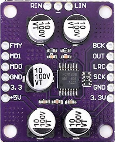
The PCM1808 is a 24-bit audio analog-to-digital converter (ADC) designed for high-performance audio applications. It converts analog audio signals into digital data with exceptional accuracy, low distortion, and high dynamic range. This makes it an ideal choice for professional audio equipment, consumer electronics, and other applications requiring high-quality audio signal processing.
Explore Projects Built with PCM1808
 Open Project in Cirkit Designer
 Open Project in Cirkit Designer
 Open Project in Cirkit Designer
 Open Project in Cirkit Designer
Explore Projects Built with PCM1808
Open Project in Cirkit DesignerOpen Project in Cirkit DesignerOpen Project in Cirkit DesignerOpen Project in Cirkit DesignerCommon Applications
- Professional audio recording equipment
- Consumer audio devices (e.g., home theater systems, audio interfaces)
- Musical instruments with digital output
- Voice recognition systems
- Audio signal processing and analysis
Technical Specifications
Key Technical Details
| Parameter | Value |
|---|---|
| Resolution | 24-bit |
| Sampling Rate | 8 kHz to 96 kHz |
| Dynamic Range | 99 dB (typical) |
| Total Harmonic Distortion + Noise (THD+N) | -93 dB (typical) |
| Input Voltage Range | 0.6 Vpp to 2.1 Vpp (adjustable) |
| Power Supply Voltage | 3.3 V (typical) |
| Power Consumption | 13 mW (typical) |
| Operating Temperature Range | -25°C to 85°C |
| Package Type | 14-pin TSSOP |
Pin Configuration and Descriptions
The PCM1808 is housed in a 14-pin TSSOP package. Below is the pin configuration and description:
| Pin No. | Name | Type | Description |
|---|---|---|---|
| 1 | VINL | Input | Left-channel analog audio input |
| 2 | VINR | Input | Right-channel analog audio input |
| 3 | VREF1 | Output | Reference voltage output 1 |
| 4 | VREF2 | Output | Reference voltage output 2 |
| 5 | AGND | Ground | Analog ground |
| 6 | VCC | Power | Power supply (3.3 V) |
| 7 | SCKI | Input | System clock input |
| 8 | BCK | Input | Audio data bit clock |
| 9 | LRCK | Input | Left-right clock for audio data |
| 10 | DOUT | Output | Digital audio data output |
| 11 | DGND | Ground | Digital ground |
| 12 | FORMAT | Input | Audio data format selection |
| 13 | MODE0 | Input | Mode selection pin 0 |
| 14 | MODE1 | Input | Mode selection pin 1 |
Usage Instructions
How to Use the PCM1808 in a Circuit
- Power Supply: Connect the VCC pin to a stable 3.3 V power source and ensure proper decoupling capacitors are placed near the pin to reduce noise.
- Grounding: Connect AGND and DGND to a common ground plane to minimize noise interference.
- Analog Inputs: Connect the left and right analog audio signals to the VINL and VINR pins, respectively. Use appropriate coupling capacitors to block DC components.
- Clock Signals: Provide a system clock (SCKI) and synchronize the bit clock (BCK) and left-right clock (LRCK) with the audio data format.
- Audio Data Output: The digital audio data is output through the DOUT pin. Connect this pin to a microcontroller, DSP, or other digital audio processing device.
- Mode and Format Selection: Configure the FORMAT, MODE0, and MODE1 pins to select the desired audio data format and operating mode.
Important Considerations
- Use low-noise power supplies and proper grounding techniques to achieve optimal performance.
- Ensure the input audio signal levels are within the specified range to avoid distortion or clipping.
- Use high-quality clock sources to minimize jitter and improve audio fidelity.
- Place decoupling capacitors close to the power supply pins to reduce noise.
Example: Connecting PCM1808 to Arduino UNO
The PCM1808 can be interfaced with an Arduino UNO to process audio data. Below is an example of how to configure the Arduino to read audio data from the PCM1808.
// Example code to interface PCM1808 with Arduino UNO
// This code assumes the PCM1808 is configured for I2S audio data output

#include <I2S.h> // Include the I2S library for audio data processing

void setup() {
  // Initialize serial communication for debugging
  Serial.begin(9600);

  // Initialize I2S in slave mode to receive audio data
  if (!I2S.begin(I2S_PHILIPS_MODE, 44100)) {
    Serial.println("Failed to initialize I2S!");
    while (1); // Halt execution if I2S initialization fails
  }

  Serial.println("I2S initialized successfully!");
}

void loop() {
  // Check if audio data is available
  if (I2S.available()) {
    int sample = I2S.read(); // Read a single audio sample
    Serial.println(sample); // Print the sample value for debugging
  }
}
Note: The Arduino UNO requires an external I2S interface module to communicate with the PCM1808, as it does not natively support I2S.
Troubleshooting and FAQs
Common Issues and Solutions
No Audio Output:
- Verify that the power supply is stable and within the specified range.
- Check the clock signals (SCKI, BCK, LRCK) for proper synchronization.
- Ensure the input audio signal is connected correctly and within the specified range.
Distorted Audio:
- Confirm that the input signal levels are not exceeding the maximum input voltage range.
- Check for noise or interference in the power supply or ground connections.
- Use high-quality coupling capacitors for the analog inputs.
I2S Communication Issues:
- Verify the FORMAT, MODE0, and MODE1 pin configurations match the expected I2S format.
- Ensure the microcontroller or DSP is configured correctly for I2S communication.
FAQs
Q: Can the PCM1808 operate at sampling rates higher than 96 kHz?
A: No, the PCM1808 supports sampling rates from 8 kHz to 96 kHz. For higher sampling rates, consider using a different ADC.
Q: What is the recommended input impedance for the analog inputs?
A: The PCM1808 has an internal input impedance of approximately 10 kΩ. Ensure the source impedance is low enough to avoid signal degradation.
Q: Can the PCM1808 be used with a 5 V power supply?
A: No, the PCM1808 is designed to operate with a 3.3 V power supply. Using a 5 V supply may damage the device.
Q: How do I minimize noise in the audio output?
A: Use proper grounding techniques, low-noise power supplies, and high-quality clock sources to reduce noise and improve audio fidelity.