How to Use Haptic Controller Breakout: Examples, Pinouts, and Specs
Introduction
A Haptic Controller Breakout is a compact module designed to enable the integration of haptic feedback into electronic projects. It works by driving vibration motors or linear resonant actuators (LRAs) to produce tactile sensations, enhancing user interaction. This component is commonly used in applications such as gaming controllers, smartphones, wearable devices, and other interactive systems where touch-based feedback is essential.
By interfacing with microcontrollers, the Haptic Controller Breakout allows developers to create dynamic and responsive feedback systems, making it a valuable tool for improving user experience in modern electronics.
Explore Projects Built with Haptic Controller Breakout
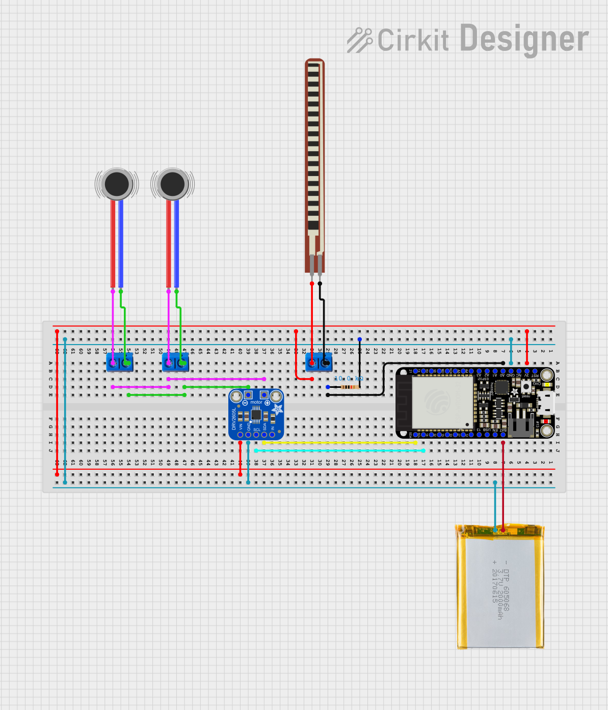

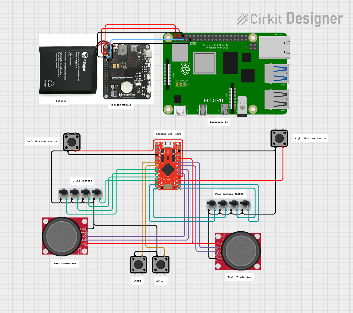
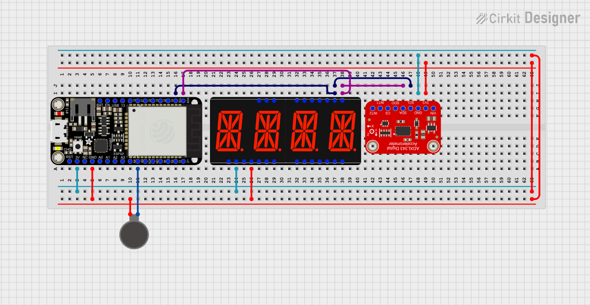
Explore Projects Built with Haptic Controller Breakout
Technical Specifications
Below are the key technical details of a typical Haptic Controller Breakout module:
- Operating Voltage: 3.0V to 5.5V
- Output Drive: Supports ERM (Eccentric Rotating Mass) motors and LRAs
- Communication Interface: I2C or PWM
- Current Consumption: Typically 10mA to 50mA (depending on the motor/actuator)
- Frequency Range: 45Hz to 300Hz (for LRA resonance tuning)
- Dimensions: Compact breakout board, typically 20mm x 20mm
- Additional Features: Built-in waveform library, overcurrent protection, and thermal shutdown
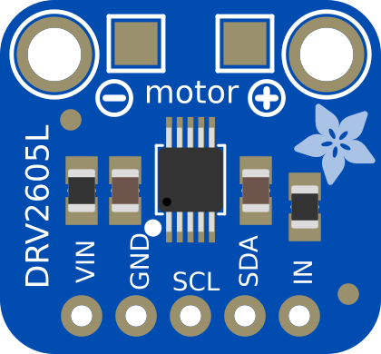
Pin Configuration and Descriptions
The Haptic Controller Breakout typically has the following pin layout:
| Pin Name | Description |
|---|---|
| VCC | Power supply input (3.0V to 5.5V). Connect to the microcontroller's power pin. |
| GND | Ground connection. Connect to the microcontroller's ground. |
| SDA | I2C data line. Used for communication with the microcontroller. |
| SCL | I2C clock line. Used for communication with the microcontroller. |
| IN/TRIG | PWM input or trigger pin for simple haptic effects. |
| OUT+ | Positive output for the vibration motor or LRA. |
| OUT- | Negative output for the vibration motor or LRA. |
Usage Instructions
How to Use the Component in a Circuit
- Power the Module: Connect the
VCCpin to a 3.3V or 5V power source and theGNDpin to ground. - Connect to a Microcontroller:
- For I2C communication, connect the
SDAandSCLpins to the corresponding I2C pins on your microcontroller. - Alternatively, use the
IN/TRIGpin for simple PWM-based control.
- For I2C communication, connect the
- Connect the Actuator: Attach the vibration motor or LRA to the
OUT+andOUT-pins. - Program the Microcontroller: Use the appropriate library or code to send commands to the Haptic Controller Breakout.
Important Considerations and Best Practices
- Voltage Compatibility: Ensure the module's operating voltage matches your microcontroller's power supply.
- Actuator Selection: Use an actuator (ERM or LRA) that matches the module's output specifications.
- I2C Pull-Up Resistors: If not already present on the breakout board, add pull-up resistors (typically 4.7kΩ) to the
SDAandSCLlines. - Thermal Management: Avoid prolonged high-current operation to prevent overheating.
- Waveform Library: Many haptic controllers include pre-programmed waveforms. Refer to the datasheet for details on how to use them.
Example Code for Arduino UNO
Below is an example of how to control the Haptic Controller Breakout using I2C communication with an Arduino UNO:
#include <Wire.h> // Include the Wire library for I2C communication

#define HAPTIC_ADDR 0x5A // Replace with the I2C address of your Haptic Controller

void setup() {
  Wire.begin(); // Initialize I2C communication
  Serial.begin(9600); // Initialize serial communication for debugging

  // Send initialization commands to the Haptic Controller
  Wire.beginTransmission(HAPTIC_ADDR);
  Wire.write(0x01); // Example register: Set the device to active mode
  Wire.write(0x00); // Example value: Default configuration
  Wire.endTransmission();

  Serial.println("Haptic Controller Initialized");
}

void loop() {
  // Example: Trigger a haptic effect
  Wire.beginTransmission(HAPTIC_ADDR);
  Wire.write(0x03); // Example register: Play waveform
  Wire.write(0x10); // Example value: Waveform ID
  Wire.endTransmission();

  delay(1000); // Wait for 1 second before triggering again
}
Note: Refer to the specific datasheet of your Haptic Controller Breakout for the correct I2C address, register map, and waveform IDs.
Troubleshooting and FAQs
Common Issues and Solutions
No Vibration Output:
- Cause: Incorrect wiring or actuator connection.
- Solution: Double-check the connections to the
OUT+andOUT-pins. Ensure the actuator is functional.
I2C Communication Fails:
- Cause: Incorrect I2C address or missing pull-up resistors.
- Solution: Verify the I2C address in the code and ensure pull-up resistors are present on the
SDAandSCLlines.
Overheating:
- Cause: Prolonged high-current operation.
- Solution: Reduce the duty cycle or use a lower-power actuator.
Unresponsive Module:
- Cause: Incorrect power supply voltage.
- Solution: Ensure the
VCCpin is supplied with a voltage within the specified range (3.0V to 5.5V).
FAQs
Can I use this module with a 3.3V microcontroller? Yes, the module supports a wide operating voltage range (3.0V to 5.5V), making it compatible with both 3.3V and 5V systems.
What types of actuators can I use? The module supports both ERM motors and LRAs. Ensure the actuator's specifications match the module's output capabilities.
Do I need additional components to use this module? If using I2C, you may need pull-up resistors for the
SDAandSCLlines if they are not already included on the breakout board.How do I select a waveform? Refer to the module's datasheet for a list of pre-programmed waveforms and their corresponding IDs. Use I2C commands to select and play a waveform.
By following this documentation, you can successfully integrate the Haptic Controller Breakout into your projects and create engaging tactile feedback systems.