How to Use MG996R: Examples, Pinouts, and Specs
Introduction
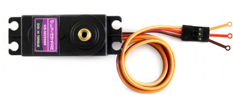
The MG996R is a robust high-torque digital servo motor widely used in the field of radio-controlled (RC) models, robotics, and automation. With its metal gears, the servo is designed for durability and can handle a substantial load, making it an ideal choice for applications requiring precise motion control and reliability. It is capable of rotating up to 180 degrees, offering a wide range of motion for various mechanical setups.
Explore Projects Built with MG996R
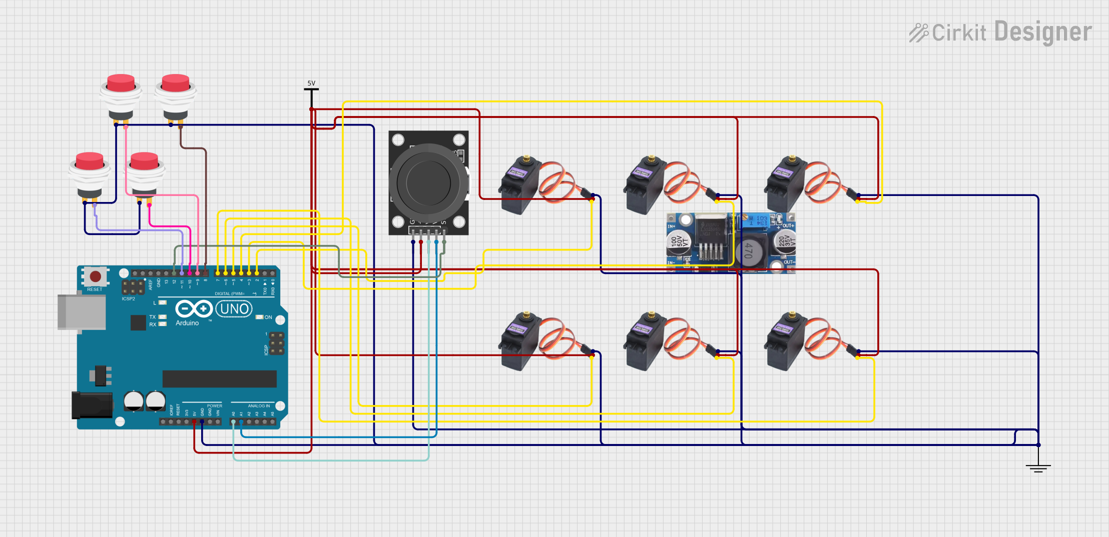
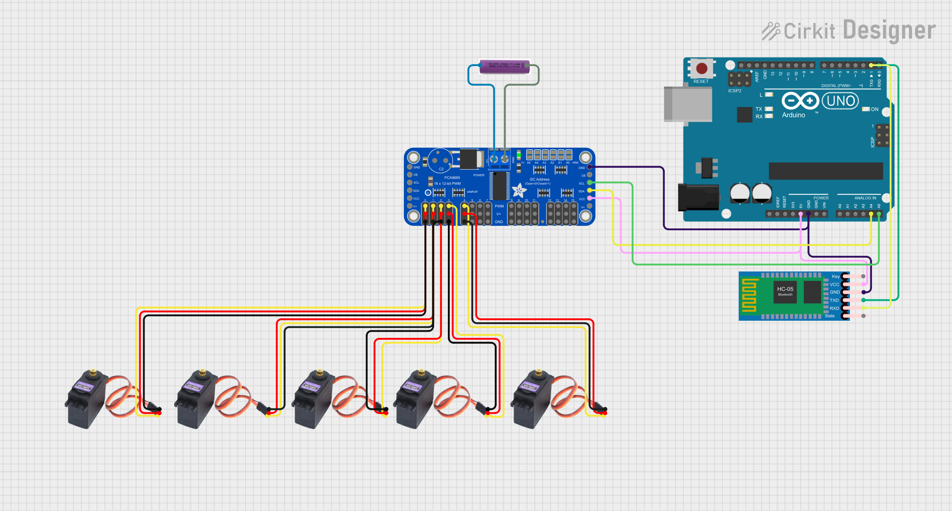
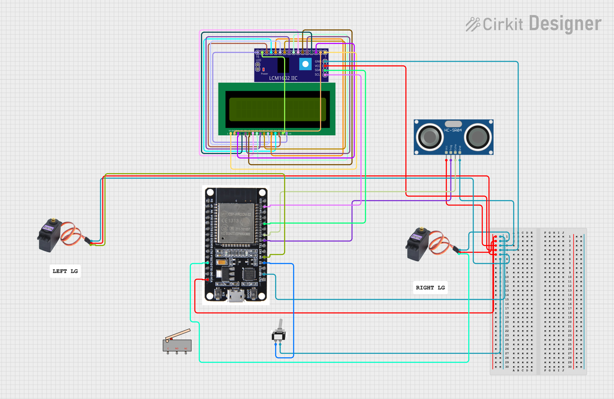

Explore Projects Built with MG996R
Common Applications and Use Cases
- Steering and throttle control for RC cars, boats, and airplanes
- Actuators for robotic arms and legs
- Pan and tilt mechanisms for cameras and sensors
- Animatronics and custom hobby projects
Technical Specifications
Key Technical Details
- Operating Voltage: 4.8V to 7.2V
- Stall Torque: 9.4 kg-cm (4.8V), 11 kg-cm (6V)
- Operating Speed: 0.17 sec/60° (4.8V), 0.14 sec/60° (6V)
- Temperature Range: -30°C to +60°C
- Weight: 55g
- Dimensions: 40.7 x 19.7 x 42.9 mm
Pin Configuration and Descriptions
| Pin Number | Signal | Description |
|---|---|---|
| 1 | Ground (GND) | Connect to the ground of the power supply |
| 2 | Power (VCC) | Connect to the positive of the power supply |
| 3 | Signal (PWM) | Connect to the PWM signal output from a controller |
Usage Instructions
How to Use the Component in a Circuit
- Power Supply: Connect the power pin (VCC) to a suitable power supply within the operating voltage range. Ensure the ground pin (GND) is connected to the common ground of the system.
- Signal Connection: Connect the signal pin (PWM) to a PWM-capable output on a microcontroller, such as an Arduino UNO.
- Mounting: Secure the servo motor to your project using the mounting holes provided on the servo casing.
Important Considerations and Best Practices
- Power Requirements: Always use a regulated power supply to prevent damage due to voltage spikes.
- Current Draw: Be aware of the current draw, especially under load, to ensure the power supply can handle the servo's requirements.
- Signal Pulse Width: The typical pulse width for controlling the MG996R ranges from 1ms to 2ms, corresponding to 0° and 180°, respectively.
- Avoid Stalling: Prevent the servo from stalling at its endpoints, as this can lead to overheating and damage.
Example Code for Arduino UNO
#include <Servo.h>

Servo myservo;  // Create servo object to control the MG996R

void setup() {
  myservo.attach(9);  // Attaches the servo on pin 9 to the servo object
}

void loop() {
  myservo.write(0);   // Turn servo to 0 degrees
  delay(1000);        // Wait 1 second
  myservo.write(90);  // Turn servo to 90 degrees (middle position)
  delay(1000);        // Wait 1 second
  myservo.write(180); // Turn servo to 180 degrees
  delay(1000);        // Wait 1 second
}
Troubleshooting and FAQs
Common Issues Users Might Face
- Servo not responding: Ensure all connections are secure and the power supply is within the specified voltage range.
- Erratic Movements: Check for any signal interference or inconsistencies in the PWM signal from the controller.
- Overheating: If the servo is overheating, reduce the load or duty cycle to prevent damage.
Solutions and Tips for Troubleshooting
- Power Supply Issues: Use a multimeter to verify the voltage and current supplied to the servo.
- Signal Integrity: Use an oscilloscope to check the PWM signal's quality and ensure it matches the expected pulse width.
- Mechanical Binding: Ensure that the servo is not mechanically obstructed or overloaded.
FAQs
Q: Can I control the MG996R with a standard RC transmitter and receiver? A: Yes, the MG996R can be controlled using standard RC equipment by connecting it to the receiver's appropriate channel.
Q: What is the maximum angle the MG996R can rotate? A: The MG996R can rotate up to 180 degrees, but the actual range may vary slightly depending on the controller and signal calibration.
Q: How do I calibrate the servo for precise movements? A: Calibration involves adjusting the PWM signal's pulse width to match the servo's endpoints accurately. This can be done through trial and error or by using a servo tester.
Q: Can the MG996R be used continuously for long periods? A: While the MG996R is durable, it is not designed for continuous rotation or prolonged use without rest. Overuse can lead to overheating and wear out the gears faster.