How to Use KY-017: Examples, Pinouts, and Specs
Introduction
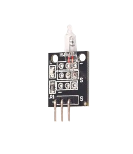
The KY-017 is a temperature sensor module that utilizes the LM35 temperature sensor. It provides an analog output that is directly proportional to the temperature in degrees Celsius. This module is widely used in temperature monitoring and control applications due to its simplicity, accuracy, and ease of integration into electronic circuits.
Explore Projects Built with KY-017


Explore Projects Built with KY-017
Common Applications and Use Cases
- Environmental temperature monitoring
- Home automation systems
- Industrial temperature control
- Weather stations
- Educational projects and prototyping
Technical Specifications
The KY-017 module is based on the LM35 temperature sensor, which is known for its linear output and high accuracy. Below are the key technical details:
| Parameter | Value |
|---|---|
| Operating Voltage | 4V to 30V |
| Output Voltage Range | 0V to 1.5V (for 0°C to 150°C) |
| Temperature Range | 0°C to 100°C (module-specific) |
| Accuracy | ±0.5°C (at 25°C) |
| Output Type | Analog |
| Dimensions | 18.5mm x 15mm x 10mm |
Pin Configuration and Descriptions
The KY-017 module has three pins, as described in the table below:
| Pin | Name | Description |
|---|---|---|
| 1 | VCC | Power supply pin (4V to 30V) |
| 2 | GND | Ground pin |
| 3 | OUT | Analog output pin, provides voltage proportional to |
| the temperature in degrees Celsius |
Usage Instructions
How to Use the KY-017 in a Circuit
- Power the Module: Connect the
VCCpin to a 5V power supply and theGNDpin to the ground of your circuit. - Read the Output: Connect the
OUTpin to an analog input pin of a microcontroller (e.g., Arduino UNO) to read the temperature as an analog voltage. - Convert Voltage to Temperature: The output voltage is proportional to the temperature, with a scale factor of 10mV/°C. For example, an output of 250mV corresponds to 25°C.
Important Considerations and Best Practices
- Ensure the module is powered within its operating voltage range (4V to 30V).
- Avoid exposing the sensor to temperatures beyond its specified range to prevent damage.
- Use a stable power supply to minimize noise in the analog output.
- If using long wires, consider shielding to reduce interference.
Example Code for Arduino UNO
The following code demonstrates how to use the KY-017 module with an Arduino UNO to read and display the temperature:
// Define the analog pin connected to the KY-017 OUT pin
const int sensorPin = A0;

void setup() {
  Serial.begin(9600); // Initialize serial communication at 9600 baud
}

void loop() {
  int sensorValue = analogRead(sensorPin); // Read the analog value from the sensor
  float voltage = sensorValue * (5.0 / 1023.0); // Convert ADC value to voltage
  float temperature = voltage * 100.0; // Convert voltage to temperature (10mV/°C)

  // Print the temperature to the Serial Monitor
  Serial.print("Temperature: ");
  Serial.print(temperature);
  Serial.println(" °C");

  delay(1000); // Wait for 1 second before the next reading
}
Notes on the Code
- The
analogRead()function reads the sensor's output voltage as a 10-bit ADC value (0-1023). - The voltage is calculated by scaling the ADC value to the Arduino's reference voltage (5V).
- The temperature is derived by multiplying the voltage by 100, as the LM35 outputs 10mV per degree Celsius.
Troubleshooting and FAQs
Common Issues and Solutions
No Output or Incorrect Readings
- Cause: Incorrect wiring or loose connections.
- Solution: Double-check the connections, ensuring
VCC,GND, andOUTare properly connected.
Fluctuating Temperature Readings
- Cause: Electrical noise or unstable power supply.
- Solution: Use a decoupling capacitor (e.g., 0.1µF) between
VCCandGNDto stabilize the power supply.
Output Voltage Does Not Match Expected Temperature
- Cause: Calibration issue or incorrect conversion formula.
- Solution: Verify the conversion formula and ensure the Arduino's reference voltage is accurate.
Sensor Overheating
- Cause: Operating the module beyond its voltage or temperature limits.
- Solution: Ensure the module is powered within the specified voltage range and used within the temperature range.
FAQs
Q: Can the KY-017 measure negative temperatures?
A: No, the KY-017 module is designed to measure temperatures in the range of 0°C to 100°C. For negative temperatures, additional circuitry or a different sensor is required.
Q: Can I use the KY-017 with a 3.3V microcontroller?
A: Yes, the KY-017 can operate at 3.3V, but the output voltage range will be lower, which may reduce resolution. Ensure the microcontroller's ADC can handle the reduced range.
Q: How accurate is the KY-017 module?
A: The LM35 sensor provides an accuracy of ±0.5°C at 25°C. However, external factors like noise and power supply stability can affect the overall accuracy.
Q: Is the KY-017 suitable for outdoor use?
A: The KY-017 is not weatherproof. For outdoor applications, additional protection (e.g., an enclosure) is required to shield the module from moisture and extreme conditions.