How to Use Adafruit Feather M0 Adalogger: Examples, Pinouts, and Specs
Introduction
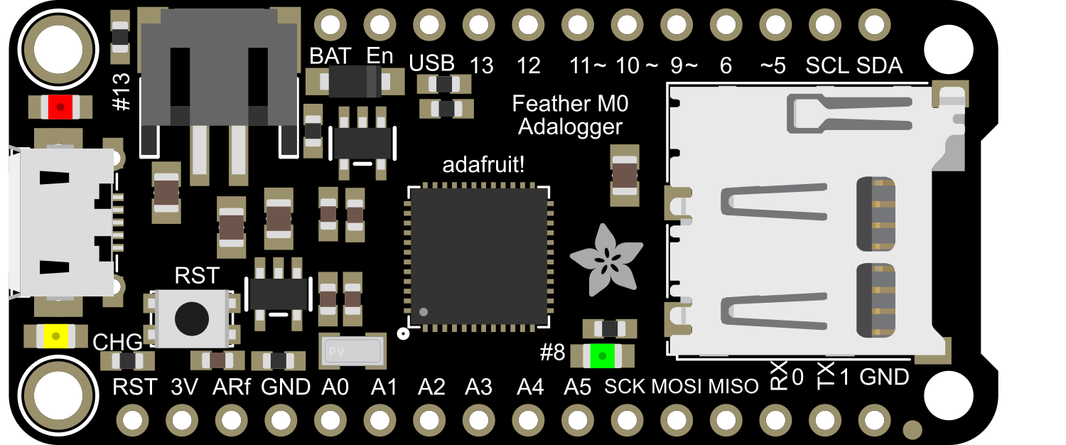
The Adafruit Feather M0 Adalogger is a compact and versatile microcontroller board powered by an ARM Cortex-M0 processor. Designed for low-power applications, it is an excellent choice for projects requiring efficient data logging capabilities. The board features an onboard SD card slot, making it ideal for applications such as environmental monitoring, IoT data collection, and portable data logging systems. Its small form factor and compatibility with the Feather ecosystem make it a popular choice among hobbyists and professionals alike.
Explore Projects Built with Adafruit Feather M0 Adalogger

Explore Projects Built with Adafruit Feather M0 Adalogger
Common Applications and Use Cases
- Environmental data logging (e.g., temperature, humidity, pressure)
- IoT devices with data storage requirements
- Portable sensor systems
- GPS data logging
- Prototyping low-power embedded systems
Technical Specifications
The Adafruit Feather M0 Adalogger is built to deliver reliable performance in a compact design. Below are its key technical specifications:
Key Technical Details
| Specification | Value |
|---|---|
| Microcontroller | ATSAMD21G18 ARM Cortex-M0 |
| Operating Voltage | 3.3V |
| Clock Speed | 48 MHz |
| Flash Memory | 256 KB |
| SRAM | 32 KB |
| Power Supply | USB or LiPo battery (3.7V) |
| SD Card Slot | Supports microSD cards (FAT16/FAT32) |
| GPIO Pins | 20 (8 PWM-capable, 10 analog inputs) |
| Communication Interfaces | UART, I2C, SPI |
| USB Interface | Micro USB (native USB support) |
| Dimensions | 51mm x 23mm x 8mm |
| Weight | 5.7g |
Pin Configuration and Descriptions
The Adafruit Feather M0 Adalogger has a total of 20 GPIO pins, each with specific functions. Below is a summary of the pin configuration:
| Pin Number | Label | Description |
|---|---|---|
| 1 | A0 | Analog input 0 / Digital GPIO |
| 2 | A1 | Analog input 1 / Digital GPIO |
| 3 | A2 | Analog input 2 / Digital GPIO |
| 4 | A3 | Analog input 3 / Digital GPIO |
| 5 | A4 (SDA) | Analog input 4 / I2C Data |
| 6 | A5 (SCL) | Analog input 5 / I2C Clock |
| 7 | D5 | Digital GPIO / PWM |
| 8 | D6 | Digital GPIO / PWM |
| 9 | D9 | Digital GPIO / PWM |
| 10 | D10 | Digital GPIO / PWM |
| 11 | D11 (MOSI) | SPI MOSI |
| 12 | D12 (MISO) | SPI MISO |
| 13 | D13 (SCK) | SPI Clock / LED |
| 14 | RX | UART Receive |
| 15 | TX | UART Transmit |
| 16 | EN | Enable pin for power control |
| 17 | BAT | Battery voltage monitoring |
| 18 | USB | USB power input |
| 19 | 3V3 | 3.3V power output |
| 20 | GND | Ground |
Usage Instructions
The Adafruit Feather M0 Adalogger is easy to integrate into a variety of projects. Follow the steps below to get started:
How to Use the Component in a Circuit
Powering the Board:
- Connect the board to a computer or USB power source using a Micro USB cable.
- Alternatively, connect a 3.7V LiPo battery to the JST connector for portable operation.
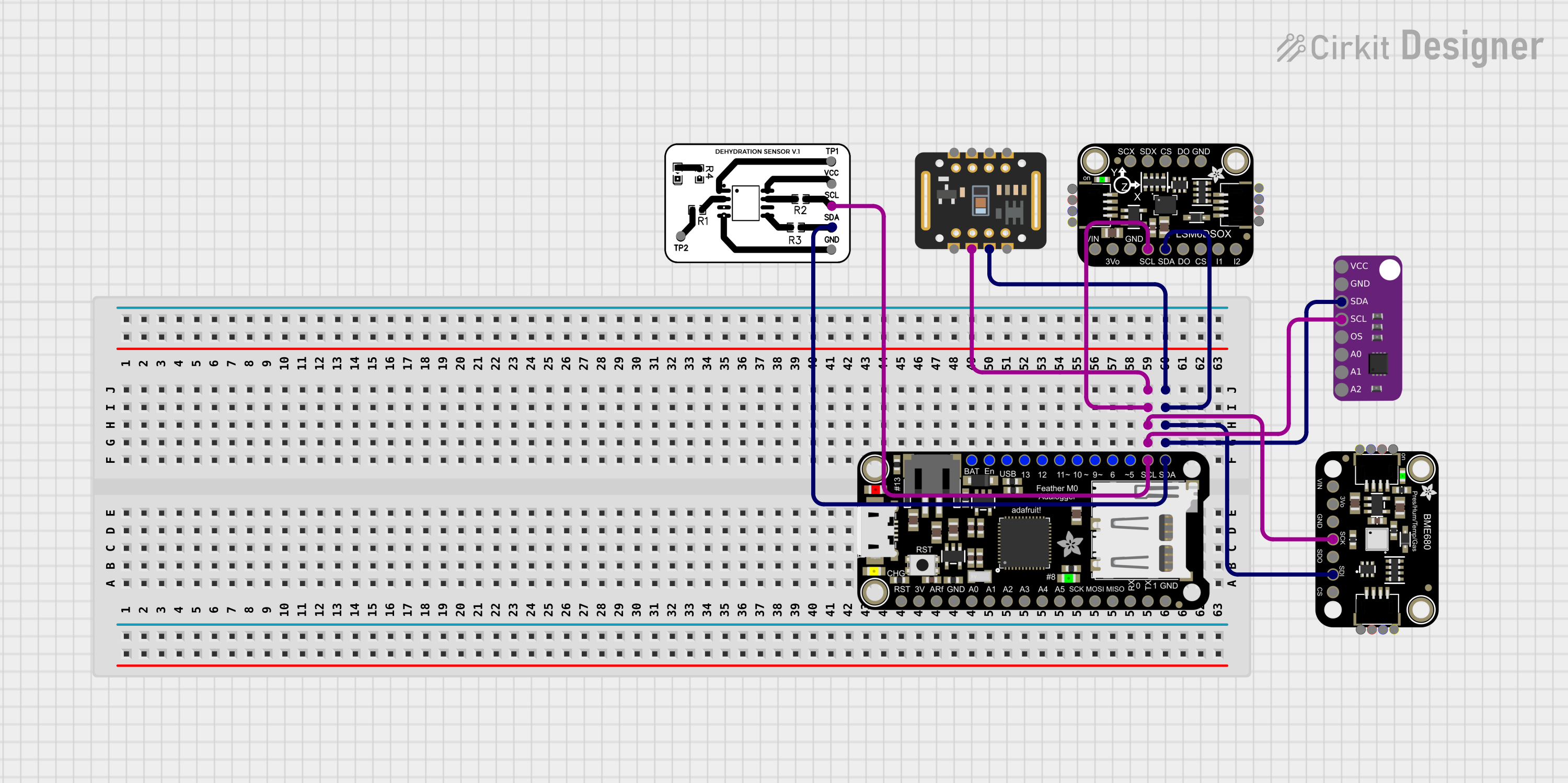
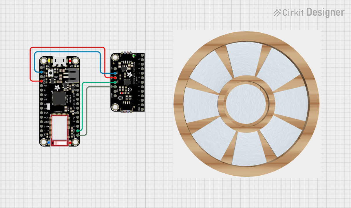
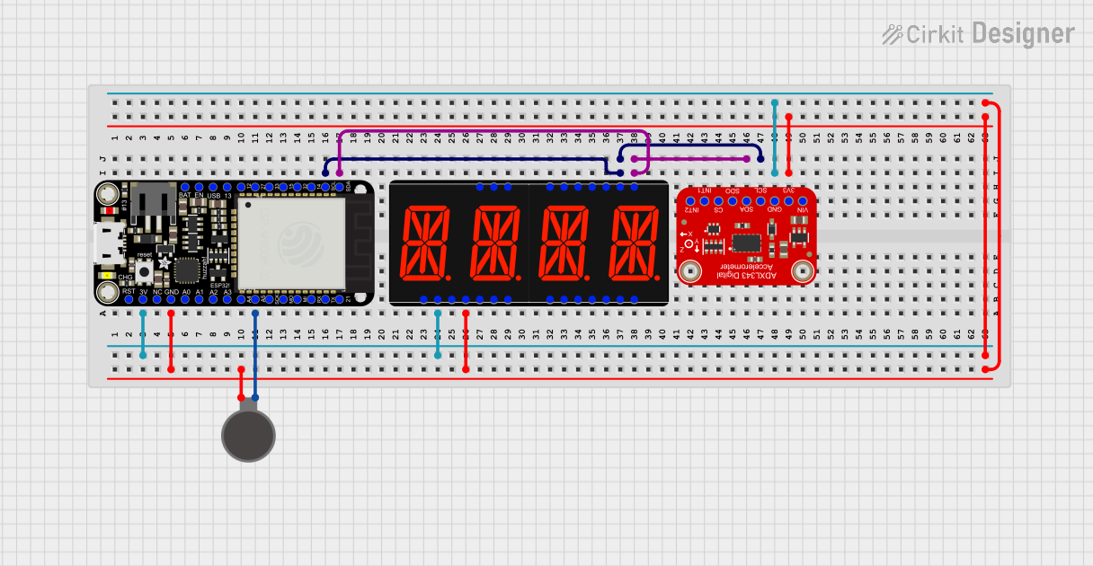
Connecting Peripherals:
- Use the GPIO pins to connect sensors, actuators, or other peripherals.
- For data logging, insert a microSD card into the onboard SD card slot.
Programming the Board:
- Install the Arduino IDE and add the Adafruit SAMD Boards package via the Board Manager.
- Select "Adafruit Feather M0" as the board type in the Arduino IDE.
- Write and upload your code to the board using the Micro USB connection.
Data Logging:
- Use the SD library in Arduino to write data to the microSD card.
- Ensure the microSD card is formatted as FAT16 or FAT32.
Important Considerations and Best Practices
- Voltage Levels: The GPIO pins operate at 3.3V. Avoid applying 5V to any pin to prevent damage.
- Battery Monitoring: Use the
BATpin to monitor the LiPo battery voltage. - SD Card Compatibility: Ensure the microSD card is properly formatted and inserted securely.
- Power Management: Use the
ENpin to enable or disable power to the board for low-power applications.
Example Code for Data Logging with Arduino
Below is an example of how to log data to the SD card using the Adafruit Feather M0 Adalogger:
#include <SPI.h>
#include <SD.h>

// Define the chip select pin for the SD card
const int chipSelect = 4;

void setup() {
  // Initialize serial communication for debugging
  Serial.begin(9600);
  while (!Serial) {
    // Wait for the serial port to connect (for native USB boards)
  }

  Serial.println("Initializing SD card...");

  // Check if the SD card is available
  if (!SD.begin(chipSelect)) {
    Serial.println("SD card initialization failed!");
    return;
  }
  Serial.println("SD card initialized successfully.");

  // Create or open a file on the SD card
  File dataFile = SD.open("datalog.txt", FILE_WRITE);

  // Check if the file opened successfully
  if (dataFile) {
    dataFile.println("Hello, Feather M0 Adalogger!");
    dataFile.close(); // Close the file to save changes
    Serial.println("Data written to datalog.txt");
  } else {
    Serial.println("Error opening datalog.txt");
  }
}

void loop() {
  // Add your main code here
}
Troubleshooting and FAQs
Common Issues and Solutions
SD Card Initialization Fails:
- Ensure the SD card is formatted as FAT16 or FAT32.
- Check the wiring to the SD card slot and ensure the card is inserted properly.
- Verify that the
chipSelectpin in your code matches the hardware configuration.
Board Not Recognized by Arduino IDE:
- Install the Adafruit SAMD Boards package in the Arduino IDE.
- Ensure the correct board and port are selected in the Tools menu.
Power Issues:
- Verify that the board is receiving power via USB or a LiPo battery.
- Check the
ENpin to ensure the board is not disabled.
Data Logging Errors:
- Ensure the file name used in the code is valid (8.3 filename format).
- Close files after writing to prevent data corruption.
FAQs
Q: Can I use the Feather M0 Adalogger with 5V sensors?
A: No, the GPIO pins operate at 3.3V. Use a level shifter to interface with 5V sensors.
Q: What is the maximum size of the SD card supported?
A: The board supports microSD cards formatted as FAT16 or FAT32, typically up to 32GB.
Q: How do I monitor battery voltage?
A: Read the voltage on the BAT pin using an analog input. Multiply the reading by the appropriate scaling factor to calculate the actual voltage.
Q: Can I use the Feather M0 Adalogger without a battery?
A: Yes, the board can be powered via USB alone. However, a battery is required for portable applications.