How to Use FemtoBuck LED Driver: Examples, Pinouts, and Specs
Introduction
The FemtoBuck LED Driver is a compact, efficient, and easy-to-use constant current LED driver. It is specifically designed to power a single high-power LED at a constant current of up to 350mA. The driver's simplicity makes it ideal for a wide range of applications, including architectural lighting, task lighting, and DIY projects where precise LED control is required. The FemtoBuck can be controlled via an onboard potentiometer for analog dimming or through a PWM signal for digital dimming, providing flexibility in light intensity control.
Explore Projects Built with FemtoBuck LED Driver

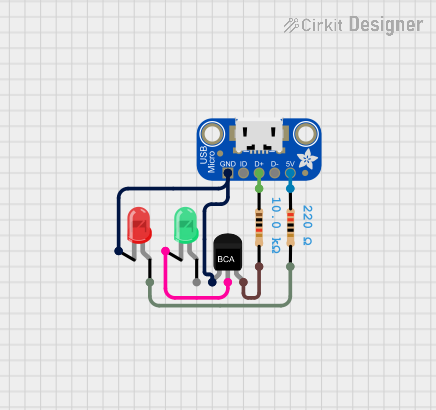
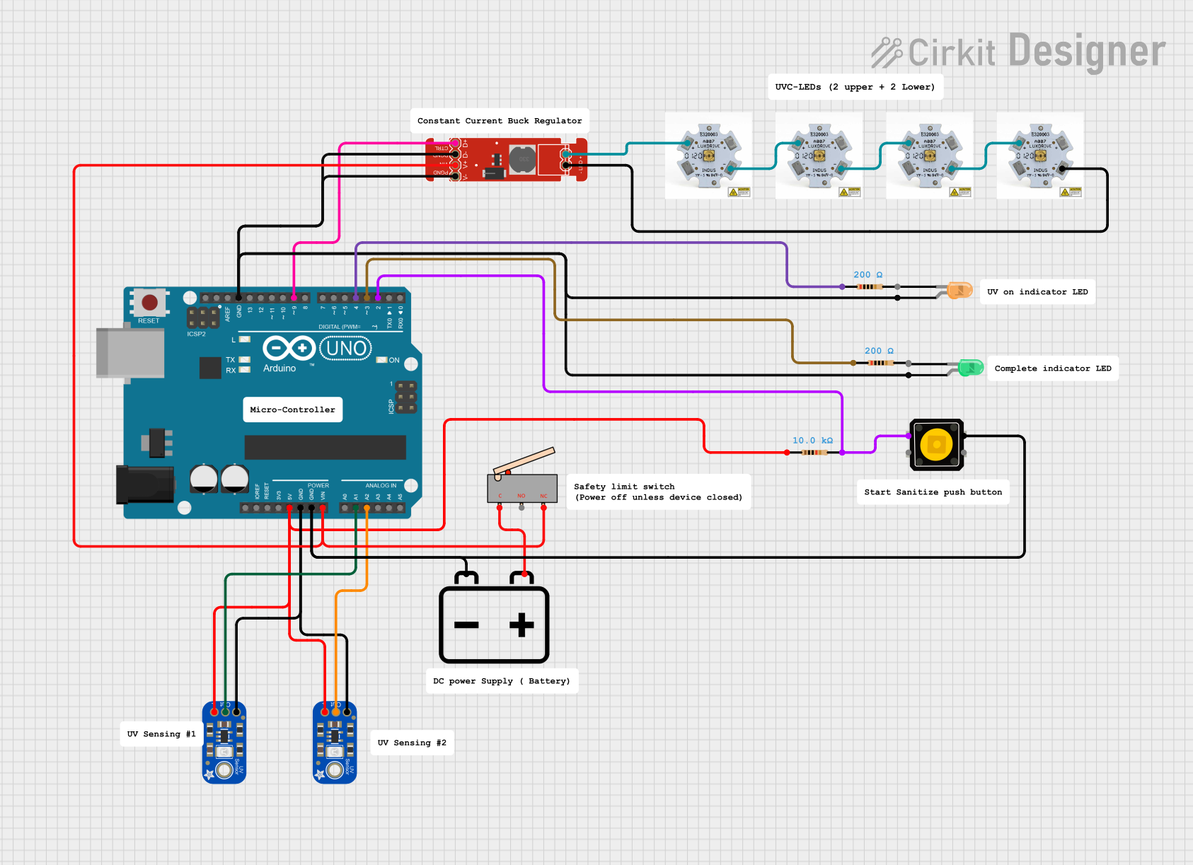
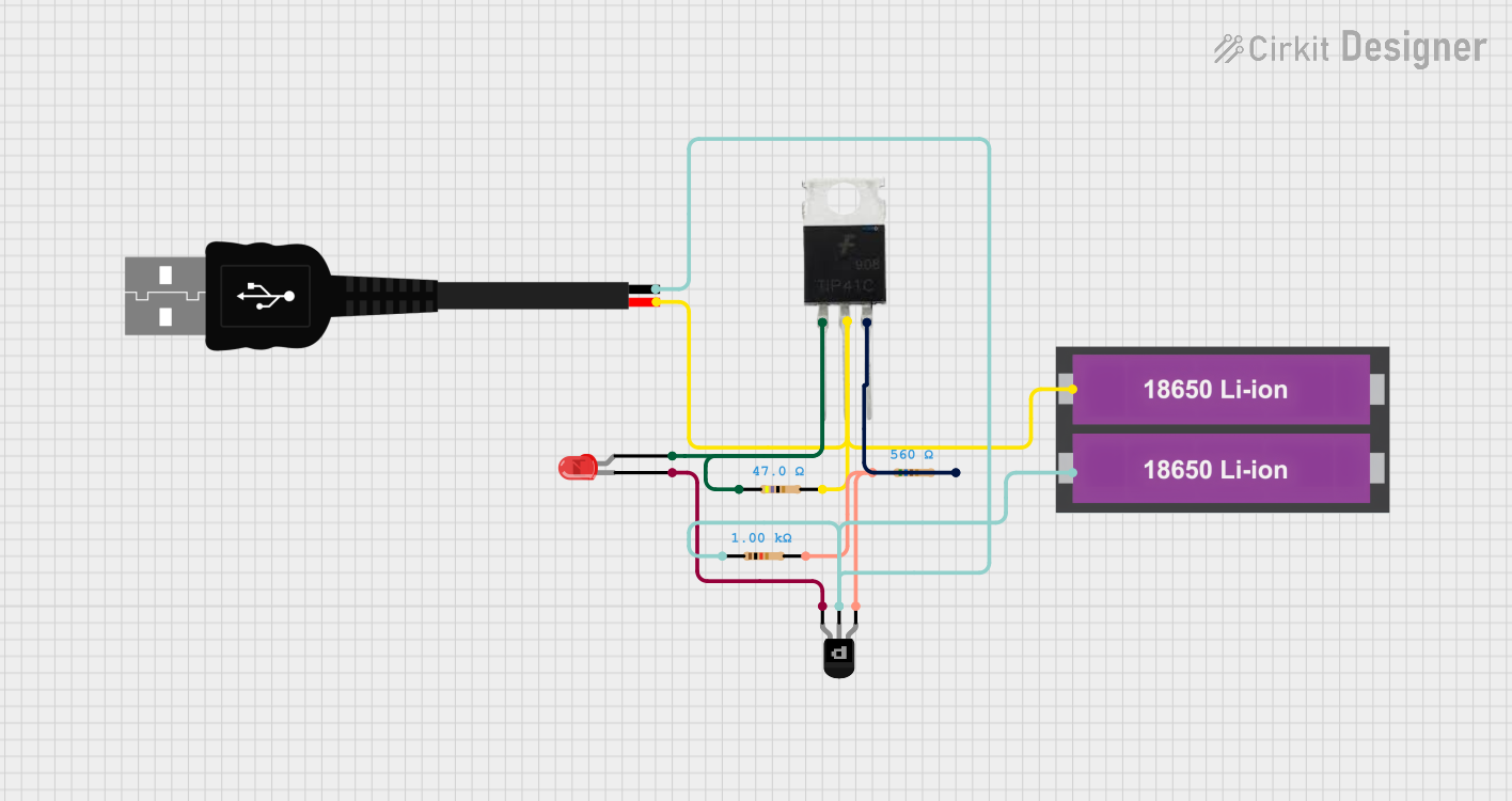
Explore Projects Built with FemtoBuck LED Driver
Technical Specifications
Key Technical Details
- Input Voltage: 6V to 36V
- Output Current: Adjustable up to 350mA
- Efficiency: Up to 95%
- Dimming Control: Analog via potentiometer, Digital via PWM
- PWM Frequency: Up to 5kHz
- Operating Temperature: -40°C to +85°C
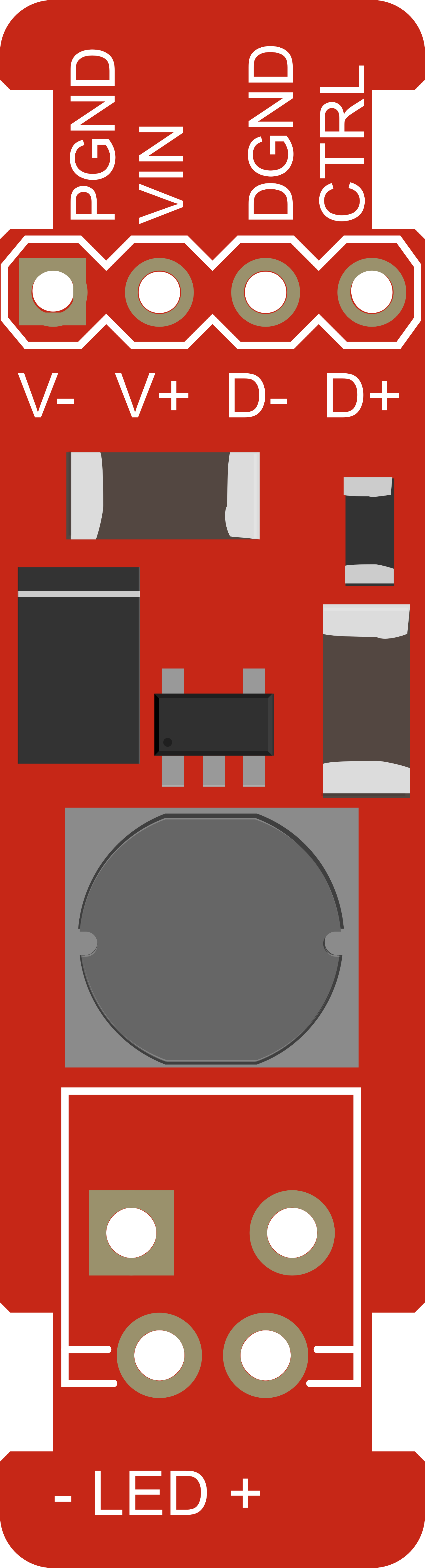
Pin Configuration and Descriptions
| Pin Number | Name | Description |
|---|---|---|
| 1 | VIN | Input voltage (6V to 36V) |
| 2 | GND | Ground connection |
| 3 | VOUT | LED positive connection |
| 4 | DIM | PWM dimming control input |
| 5 | CTRL | Analog dimming control via potentiometer |
Usage Instructions
Connecting the FemtoBuck to a Circuit
Power Connections:
- Connect the positive terminal of your power supply to the VIN pin.
- Connect the ground of your power supply to the GND pin.
LED Connections:
- Connect the anode (positive) of your LED to the VOUT pin.
- Connect the cathode (negative) of your LED to the GND pin.
Dimming Control:
- For analog dimming, connect a potentiometer to the CTRL pin.
- For digital dimming, apply a PWM signal to the DIM pin.
Important Considerations and Best Practices
- Ensure that the input voltage does not exceed 36V to prevent damage to the driver.
- Do not exceed the maximum output current of 350mA for the LED.
- Use a heat sink if necessary to manage the temperature of the LED.
- When using PWM dimming, ensure that the frequency does not exceed 5kHz.
- Always power down the circuit before making or changing connections.
Troubleshooting and FAQs
Common Issues
LED is not lighting up:
- Check connections to ensure proper polarity and secure contacts.
- Verify that the input voltage is within the specified range.
- Ensure that the LED's current and voltage ratings are compatible with the driver.
LED flickering when using PWM:
- Confirm that the PWM frequency is within the specified range.
- Check for loose connections or intermittent contacts.
Solutions and Tips for Troubleshooting
- Double-check all wiring against the pin configuration table.
- Use a multimeter to verify input voltage and output current.
- If using PWM, test with a simple on/off signal to ensure the LED can light up.
FAQs
Can I drive multiple LEDs with one FemtoBuck?
- The FemtoBuck is designed for a single LED. To drive multiple LEDs, ensure they are connected in series and the total forward voltage does not exceed the input voltage.
What should I do if the LED is too bright at the lowest dimming setting?
- You can increase the resistance of the potentiometer connected to the CTRL pin for finer control over the lower brightness levels.
Example Code for Arduino UNO
// FemtoBuck LED Driver - PWM Dimming Example

const int pwmPin = 9; // Connect DIM pin of FemtoBuck to digital pin 9

void setup() {
  pinMode(pwmPin, OUTPUT);
  analogWrite(pwmPin, 0); // Start with the LED off
}

void loop() {
  for (int brightness = 0; brightness <= 255; brightness++) {
    analogWrite(pwmPin, brightness); // Ramp up brightness
    delay(10);
  }
  for (int brightness = 255; brightness >= 0; brightness--) {
    analogWrite(pwmPin, brightness); // Ramp down brightness
    delay(10);
  }
}
This example demonstrates how to control the brightness of an LED connected to the FemtoBuck using PWM from an Arduino UNO. The analogWrite function is used to send a PWM signal to the FemtoBuck, which in turn dims the LED smoothly.