How to Use 3 phase terminal: Examples, Pinouts, and Specs
Introduction
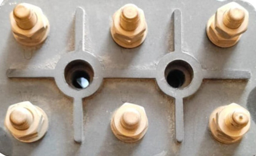
The 3 Phase Terminal by IKM is a robust electrical connector designed for use in three-phase power systems. It enables the efficient distribution of electrical power across three conductors, ensuring reliable connections in industrial and commercial environments. This component is essential for connecting motors, transformers, and other three-phase equipment, making it a critical part of power distribution networks.
Explore Projects Built with 3 phase terminal


Explore Projects Built with 3 phase terminal
Common Applications and Use Cases
- Connecting three-phase motors in industrial machinery
- Power distribution in commercial buildings
- Integration with transformers in power systems
- Use in control panels and switchgear
- Electrical connections in renewable energy systems (e.g., wind turbines)
Technical Specifications
The following table outlines the key technical specifications of the IKM 3 Phase Terminal:
| Parameter | Value |
|---|---|
| Voltage Rating | Up to 1000V AC |
| Current Rating | 10A to 250A (varies by model) |
| Number of Terminals | 3 (for three-phase connections) |
| Material | High-strength thermoplastic |
| Operating Temperature | -40°C to +85°C |
| Mounting Type | DIN rail or panel mount |
| Wire Size Compatibility | 1.5mm² to 50mm² (varies by model) |
Pin Configuration and Descriptions
The 3 Phase Terminal typically consists of three main connection points, corresponding to the three phases of the power system. The table below describes the pin configuration:
| Pin | Label | Description |
|---|---|---|
| 1 | L1 | Connection point for Phase 1 (Line 1) |
| 2 | L2 | Connection point for Phase 2 (Line 2) |
| 3 | L3 | Connection point for Phase 3 (Line 3) |
| - | PE (optional) | Protective Earth connection (if applicable) |
Usage Instructions
How to Use the Component in a Circuit
Preparation:
- Ensure the power supply is turned off before installation.
- Verify that the terminal's voltage and current ratings match the system requirements.
- Select appropriate wire sizes compatible with the terminal.
Wiring:
- Strip the insulation from the wires to expose the required length of conductor.
- Insert the wires into the respective terminals (L1, L2, L3) and tighten the screws securely.
- If the terminal includes a protective earth (PE) connection, connect the ground wire to it.
Mounting:
- Mount the terminal on a DIN rail or secure it to a panel using screws, depending on the model.
- Ensure the terminal is firmly fixed to prevent movement or disconnection.
Testing:
- Double-check all connections for tightness and correctness.
- Power on the system and verify that the connected equipment operates as expected.
Important Considerations and Best Practices
- Always follow local electrical codes and safety standards during installation.
- Use insulated tools to avoid accidental short circuits.
- Avoid over-tightening screws, as this may damage the terminal or wires.
- Periodically inspect the terminal for signs of wear, corrosion, or loose connections.
- For high-current applications, ensure proper ventilation to prevent overheating.
Example: Connecting a 3 Phase Terminal to an Arduino UNO
While the 3 Phase Terminal is not directly compatible with low-voltage microcontrollers like the Arduino UNO, it can be used in conjunction with relays or motor drivers to control three-phase equipment. Below is an example of Arduino code to control a relay module for switching a three-phase motor:
// Example Arduino code to control a relay module for a 3-phase motor
const int relayPin1 = 2; // Relay for Phase 1
const int relayPin2 = 3; // Relay for Phase 2
const int relayPin3 = 4; // Relay for Phase 3

void setup() {
  // Set relay pins as outputs
  pinMode(relayPin1, OUTPUT);
  pinMode(relayPin2, OUTPUT);
  pinMode(relayPin3, OUTPUT);

  // Initialize relays to OFF state
  digitalWrite(relayPin1, LOW);
  digitalWrite(relayPin2, LOW);
  digitalWrite(relayPin3, LOW);
}

void loop() {
  // Turn on the 3-phase motor by activating all relays
  digitalWrite(relayPin1, HIGH);
  digitalWrite(relayPin2, HIGH);
  digitalWrite(relayPin3, HIGH);
  delay(5000); // Keep motor running for 5 seconds

  // Turn off the 3-phase motor
  digitalWrite(relayPin1, LOW);
  digitalWrite(relayPin2, LOW);
  digitalWrite(relayPin3, LOW);
  delay(5000); // Wait for 5 seconds before restarting
}
Troubleshooting and FAQs
Common Issues and Solutions
Loose Connections:
- Issue: The terminal connections are loose, causing intermittent power delivery.
- Solution: Tighten the screws securely and ensure the wires are properly inserted.
Overheating:
- Issue: The terminal becomes excessively hot during operation.
- Solution: Check for overcurrent conditions or loose connections. Ensure proper ventilation.
Corrosion:
- Issue: Terminals show signs of rust or corrosion.
- Solution: Replace the terminal and ensure the environment is dry and free from moisture.
Incorrect Wiring:
- Issue: Equipment does not operate as expected.
- Solution: Verify the wiring matches the phase sequence (L1, L2, L3) and correct any errors.
FAQs
Q1: Can the 3 Phase Terminal be used for single-phase systems?
A1: Yes, it can be used for single-phase systems by connecting only one phase (e.g., L1) and neutral.
Q2: What is the maximum wire size supported?
A2: The terminal supports wire sizes up to 50mm², depending on the specific model.
Q3: Is the terminal suitable for outdoor use?
A3: The terminal is typically designed for indoor use. For outdoor applications, ensure it is housed in a weatherproof enclosure.
Q4: Can I use this terminal for DC systems?
A4: While primarily designed for AC systems, it can be used for DC systems if the voltage and current ratings are within limits.