How to Use Display 5" IPS SPI: Examples, Pinouts, and Specs
Introduction
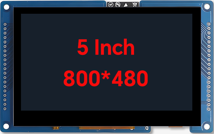
The Display 5" IPS SPI by VIEWE (Manufacturer Part ID: Display 5") is a 5-inch In-Plane Switching (IPS) display module designed for high-quality visual output. It utilizes the Serial Peripheral Interface (SPI) for communication, ensuring fast and reliable data transfer. This display offers wide viewing angles, vibrant color reproduction, and quick response times, making it ideal for a variety of embedded applications.
Explore Projects Built with Display 5" IPS SPI


Explore Projects Built with Display 5" IPS SPI
Common Applications and Use Cases
- Embedded Systems: Suitable for microcontroller-based projects such as Arduino, Raspberry Pi, and STM32.
- IoT Devices: Perfect for smart home displays, control panels, and monitoring systems.
- Portable Devices: Used in handheld devices requiring high-quality visuals.
- Industrial Applications: Ideal for HMI (Human-Machine Interface) systems.
- Prototyping: Great for developers creating visually rich interfaces.
Technical Specifications
Key Technical Details
| Parameter | Specification |
|---|---|
| Display Type | IPS (In-Plane Switching) |
| Screen Size | 5 inches |
| Resolution | 800 x 480 pixels (WVGA) |
| Interface | SPI (Serial Peripheral Interface) |
| Viewing Angle | 178° (horizontal and vertical) |
| Color Depth | 16.7M colors (24-bit RGB) |
| Operating Voltage | 3.3V to 5V |
| Backlight | LED |
| Response Time | 20ms (typical) |
| Operating Temperature | -20°C to 70°C |
| Storage Temperature | -30°C to 80°C |
Pin Configuration and Descriptions
The Display 5" IPS SPI module has a standard pin header for interfacing. Below is the pin configuration:
| Pin Number | Pin Name | Description |
|---|---|---|
| 1 | VCC | Power supply input (3.3V to 5V) |
| 2 | GND | Ground |
| 3 | CS | Chip Select (active low) |
| 4 | SCK | Serial Clock (SPI clock input) |
| 5 | MOSI | Master Out Slave In (SPI data input) |
| 6 | DC | Data/Command control pin |
| 7 | RESET | Reset signal (active low) |
| 8 | BLK | Backlight control (PWM or ON/OFF) |
Usage Instructions
How to Use the Component in a Circuit
- Power Supply: Connect the VCC pin to a 3.3V or 5V power source and the GND pin to ground.
- SPI Communication: Connect the CS, SCK, and MOSI pins to the corresponding SPI pins on your microcontroller.
- Control Pins:
- Use the DC pin to toggle between data and command modes.
- Use the RESET pin to initialize the display during startup.
- Backlight Control: Connect the BLK pin to a PWM-capable pin on your microcontroller for brightness control or directly to VCC for constant backlight.
Important Considerations and Best Practices
- Voltage Levels: Ensure the logic levels of your microcontroller match the display's voltage requirements (3.3V or 5V).
- SPI Speed: Configure the SPI clock speed according to the display's datasheet to avoid communication errors.
- Initialization Sequence: Follow the recommended initialization sequence provided in the display's datasheet or library.
- Backlight Control: Use PWM for adjustable brightness to save power and extend the backlight's lifespan.
Example Code for Arduino UNO
Below is an example of how to interface the Display 5" IPS SPI with an Arduino UNO using the popular Adafruit_GFX and Adafruit_ST7789 libraries (assuming the display uses the ST7789 driver):
#include <Adafruit_GFX.h>      // Core graphics library
#include <Adafruit_ST7789.h>   // ST7789 driver library
#include <SPI.h>               // SPI library

// Define pin connections
#define TFT_CS    10  // Chip Select pin
#define TFT_RST   9   // Reset pin
#define TFT_DC    8   // Data/Command pin

// Initialize the display object
Adafruit_ST7789 tft = Adafruit_ST7789(TFT_CS, TFT_DC, TFT_RST);

void setup() {
  // Initialize serial communication for debugging
  Serial.begin(9600);
  Serial.println("Initializing Display...");

  // Initialize the display
  tft.init(240, 320);  // Adjust resolution if necessary
  tft.setRotation(1);  // Set display orientation

  // Fill the screen with a color
  tft.fillScreen(ST77XX_BLACK);
  tft.setTextColor(ST77XX_WHITE);
  tft.setTextSize(2);
  tft.setCursor(10, 10);
  tft.println("Hello, World!");
}

void loop() {
  // Add your code here to update the display
}
Troubleshooting and FAQs
Common Issues and Solutions
Display Not Turning On:
- Cause: Incorrect power supply or loose connections.
- Solution: Verify that the VCC and GND pins are properly connected and the voltage is within the specified range.
No Output on the Screen:
- Cause: Incorrect SPI wiring or initialization sequence.
- Solution: Double-check the SPI connections and ensure the initialization code matches the display's driver.
Flickering or Dim Backlight:
- Cause: Insufficient power supply or incorrect backlight control.
- Solution: Ensure the power source can provide enough current and verify the BLK pin connection.
Distorted or Incorrect Colors:
- Cause: Incorrect SPI clock speed or data corruption.
- Solution: Adjust the SPI clock speed in your microcontroller's settings.
FAQs
Q: Can this display be used with 5V logic microcontrollers like Arduino UNO?
- A: Yes, the display supports 5V logic levels, but ensure proper wiring and initialization.
Q: What is the maximum SPI clock speed supported?
- A: Refer to the display's datasheet for the exact maximum SPI clock speed, typically up to 15-20 MHz.
Q: Is there a library available for this display?
- A: Yes, you can use libraries like
Adafruit_GFXandAdafruit_ST7789for Arduino or equivalent libraries for other platforms.
- A: Yes, you can use libraries like
Q: Can the backlight brightness be adjusted?
- A: Yes, use a PWM signal on the BLK pin for brightness control.
This concludes the documentation for the Display 5" IPS SPI by VIEWE. For further assistance, refer to the manufacturer's datasheet or contact technical support.