How to Use Hi Link 5V 3W: Examples, Pinouts, and Specs
Introduction
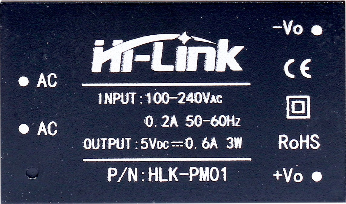
The Hi Link HLK-PM01 is a compact and efficient power supply module designed to convert AC mains voltage (100-240V AC) into a stable 5V DC output. With a power rating of 3 watts, this module is ideal for powering small electronic devices and embedded systems. Its small form factor and high efficiency make it a popular choice for applications requiring reliable DC power in a compact space.
Explore Projects Built with Hi Link 5V 3W


Explore Projects Built with Hi Link 5V 3W
Common Applications and Use Cases
- Powering microcontrollers (e.g., Arduino, ESP8266, ESP32, Raspberry Pi Pico)
- IoT devices and smart home systems
- Industrial control systems
- LED lighting and small DC motors
- Battery charging circuits
- Replacing bulky linear power supplies in compact designs
Technical Specifications
The HLK-PM01 module is designed to provide a stable and safe DC output while operating directly from AC mains. Below are its key technical details:
Electrical Specifications
| Parameter | Value |
|---|---|
| Input Voltage Range | 100V AC to 240V AC |
| Input Frequency | 50Hz to 60Hz |
| Output Voltage | 5V DC |
| Output Current | Up to 600mA |
| Output Power | 3W |
| Efficiency | ≥ 70% |
| Ripple and Noise | ≤ 50mV |
| Isolation Voltage | 3000V AC |
| Operating Temperature | -20°C to +60°C |
| Storage Temperature | -40°C to +80°C |
| Dimensions | 34mm x 20mm x 15mm |
Pin Configuration and Descriptions
The HLK-PM01 module has six pins, divided into two groups: AC input and DC output.
| Pin Number | Pin Name | Description |
|---|---|---|
| 1 | AC (L) | Live wire input for AC mains voltage |
| 2 | AC (N) | Neutral wire input for AC mains voltage |
| 3 | NC | Not connected (leave unconnected) |
| 4 | +5V | Positive 5V DC output |
| 5 | GND | Ground (0V) for DC output |
| 6 | NC | Not connected (leave unconnected) |
Note: Ensure proper isolation and safety precautions when working with AC mains voltage.
Usage Instructions
The HLK-PM01 module is straightforward to use but requires careful handling due to its direct connection to AC mains. Follow the steps below to integrate it into your circuit:
Steps to Use
Connect the AC Input:
- Connect the
AC (L)pin to the live wire of the AC mains. - Connect the
AC (N)pin to the neutral wire of the AC mains. - Ensure proper insulation and secure connections to avoid electrical hazards.
- Connect the
Connect the DC Output:
- Use the
+5Vpin to power your circuit's positive rail. - Connect the
GNDpin to the ground of your circuit.
- Use the
Verify Connections:
- Double-check all connections before powering the module.
- Ensure there are no short circuits or loose wires.
Power On:
- Apply AC mains voltage to the input pins.
- Measure the output voltage using a multimeter to confirm a stable 5V DC output.
Important Considerations and Best Practices
- Safety First: Always handle the module with care when connected to AC mains. Use proper insulation and avoid touching the module while powered.
- Heat Dissipation: Ensure adequate ventilation around the module to prevent overheating.
- Load Requirements: Do not exceed the maximum output current of 600mA to avoid damaging the module.
- Isolation: Use optocouplers or relays if interfacing the module with sensitive circuits to ensure electrical isolation.
- Testing: Test the module with a resistive load (e.g., a 10Ω, 5W resistor) before connecting it to your final circuit.
Example: Using HLK-PM01 with Arduino UNO
The HLK-PM01 can be used to power an Arduino UNO directly. Below is an example circuit and code to blink an LED using the module:
Circuit Connections
- Connect the
+5Voutput of the HLK-PM01 to the5Vpin of the Arduino UNO. - Connect the
GNDoutput of the HLK-PM01 to theGNDpin of the Arduino UNO. - Connect an LED with a 220Ω resistor to pin 13 of the Arduino UNO.
Arduino Code
// Simple LED Blink Example
// This code blinks an LED connected to pin 13 of the Arduino UNO.

void setup() {
  pinMode(13, OUTPUT); // Set pin 13 as an output pin
}

void loop() {
  digitalWrite(13, HIGH); // Turn the LED on
  delay(1000);            // Wait for 1 second
  digitalWrite(13, LOW);  // Turn the LED off
  delay(1000);            // Wait for 1 second
}
Warning: Ensure the HLK-PM01 is properly insulated and isolated from human contact when connected to AC mains.
Troubleshooting and FAQs
Common Issues and Solutions
| Issue | Possible Cause | Solution |
|---|---|---|
| No output voltage | Incorrect AC input connections | Verify live and neutral connections. |
| Output voltage fluctuates | Exceeding maximum load current | Reduce the load to within 600mA. |
| Module overheating | Poor ventilation or high ambient temp | Improve ventilation or reduce load. |
| Noise in output voltage | Insufficient filtering in the circuit | Add a capacitor (e.g., 470µF) across the output. |
FAQs
Can the HLK-PM01 power a Raspberry Pi?
- No, the HLK-PM01 cannot provide sufficient current for a Raspberry Pi, which typically requires at least 2.5A.
Is the module safe for long-term use?
- Yes, the HLK-PM01 is designed for long-term use, provided it is operated within its specified limits and proper safety precautions are followed.
Can I use the HLK-PM01 in outdoor applications?
- The module is not weatherproof. Use it in a sealed, insulated enclosure for outdoor applications.
What happens if I reverse the AC input connections?
- The module will not function correctly. Always ensure proper live and neutral connections.
By following this documentation, you can safely and effectively use the Hi Link HLK-PM01 module in your projects.