How to Use Keyestudio Bouton: Examples, Pinouts, and Specs
Introduction
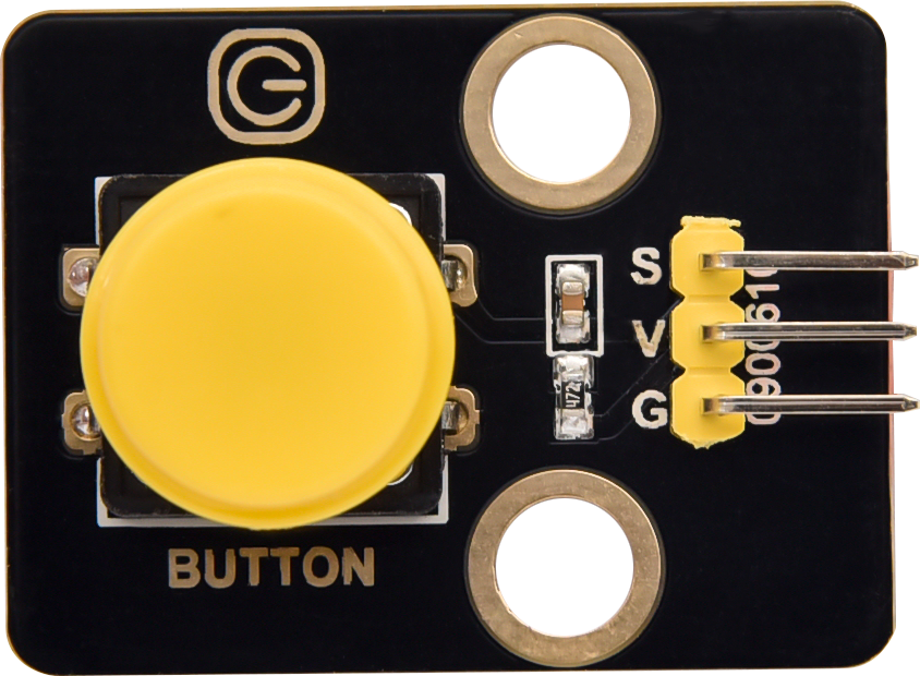
The Keyestudio Bouton is a tactile push button switch designed for user input in electronic projects. It allows for simple activation and deactivation of circuits by pressing the button. This component is widely used in prototyping, DIY electronics, and educational projects due to its ease of use and reliability.
Explore Projects Built with Keyestudio Bouton
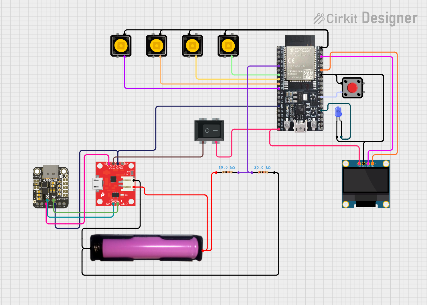
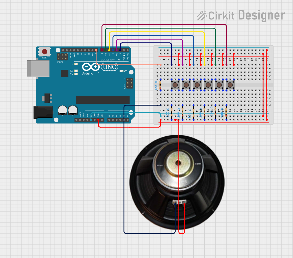

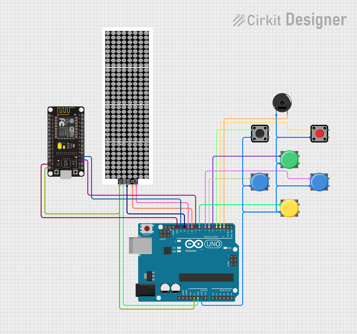
Explore Projects Built with Keyestudio Bouton
Common Applications and Use Cases
- User input for microcontroller-based projects (e.g., Arduino, Raspberry Pi)
- Triggering events or actions in circuits
- Reset or power buttons in small devices
- Educational kits for learning basic electronics
Technical Specifications
The Keyestudio Bouton is a momentary push button switch with the following specifications:
| Parameter | Value |
|---|---|
| Operating Voltage | 3.3V to 5V |
| Maximum Current | 50mA |
| Contact Resistance | ≤ 100mΩ |
| Insulation Resistance | ≥ 100MΩ |
| Operating Temperature | -25°C to +85°C |
| Dimensions | 12mm x 12mm x 7.3mm |
| Mounting Type | Through-hole or breadboard |
Pin Configuration and Descriptions
The Keyestudio Bouton has four pins, arranged in a square configuration. The pins are internally connected in pairs, as shown below:
| Pin | Description |
|---|---|
| Pin 1 | Connected to Pin 2 (internally linked) |
| Pin 2 | Connected to Pin 1 (internally linked) |
| Pin 3 | Connected to Pin 4 (internally linked) |
| Pin 4 | Connected to Pin 3 (internally linked) |
Note: When the button is pressed, the internal connection between Pin 1/2 and Pin 3/4 is completed, allowing current to flow.
Usage Instructions
How to Use the Component in a Circuit
- Connect the Button to a Breadboard:
- Place the Keyestudio Bouton on a breadboard, ensuring the pins are properly aligned.
- Wiring the Button:
- Connect one pair of pins (e.g., Pin 1 and Pin 2) to the positive voltage source (e.g., 5V).
- Connect the other pair of pins (e.g., Pin 3 and Pin 4) to the input pin of a microcontroller or the desired circuit.
- Add a pull-down resistor (e.g., 10kΩ) between the input pin and ground to ensure a stable low signal when the button is not pressed.
- Test the Button:
- When the button is pressed, the circuit will close, and the input pin will detect a HIGH signal.
Important Considerations and Best Practices
- Always use a pull-down resistor to avoid floating input signals.
- Avoid exceeding the maximum current and voltage ratings to prevent damage.
- Ensure proper debouncing in software to handle multiple rapid presses.
Example: Using the Keyestudio Bouton with an Arduino UNO
Below is an example of how to use the Keyestudio Bouton with an Arduino UNO to turn an LED on and off:
// Define pin numbers
const int buttonPin = 2;  // Pin connected to the button
const int ledPin = 13;    // Pin connected to the LED

// Variable to store button state
int buttonState = 0;

void setup() {
  pinMode(buttonPin, INPUT);  // Set button pin as input
  pinMode(ledPin, OUTPUT);    // Set LED pin as output
}

void loop() {
  // Read the state of the button
  buttonState = digitalRead(buttonPin);

  // If the button is pressed, turn on the LED
  if (buttonState == HIGH) {
    digitalWrite(ledPin, HIGH);  // Turn LED on
  } else {
    digitalWrite(ledPin, LOW);   // Turn LED off
  }
}
Note: This code assumes a pull-down resistor is used on the button pin.
Troubleshooting and FAQs
Common Issues and Solutions
Button Not Responding:
- Cause: Incorrect wiring or loose connections.
- Solution: Double-check the wiring and ensure all connections are secure.
Button Produces Erratic Behavior:
- Cause: Lack of a pull-down resistor or improper debouncing.
- Solution: Add a pull-down resistor and implement software debouncing.
Microcontroller Not Detecting Button Press:
- Cause: Incorrect pin configuration in the code.
- Solution: Verify the pin number in the code matches the physical connection.
FAQs
Q: Can I use the Keyestudio Bouton with a 3.3V system?
A: Yes, the button is compatible with both 3.3V and 5V systems.
Q: Do I need to use a pull-down resistor?
A: Yes, a pull-down resistor is recommended to ensure stable input signals when the button is not pressed.
Q: How do I debounce the button in software?
A: You can use a delay or a state-checking algorithm in your code to filter out rapid, unintended presses.
Q: Can I use the button to control high-power devices?
A: No, the button is designed for low-power applications. Use a relay or transistor to control high-power devices.