How to Use XBee : Examples, Pinouts, and Specs
Introduction
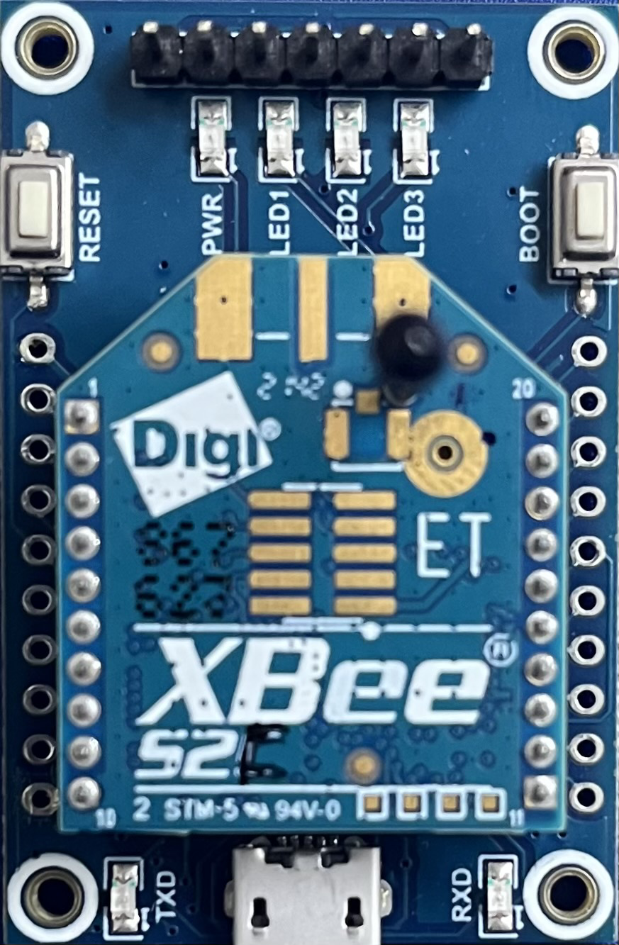
The XBee S2C, manufactured by Digi, is a versatile and reliable wireless communication module designed for a wide range of applications. It is part of the XBee series, which is known for its microcontroller-based radios that enable seamless wireless communication. Operating on the IEEE 802.15.4 standard, the XBee S2C is ideal for creating mesh networks, point-to-point, or point-to-multipoint communication systems. Its ease of use, long-range capabilities, and robust performance make it a popular choice for remote control, sensor networks, and IoT (Internet of Things) devices.
Explore Projects Built with XBee

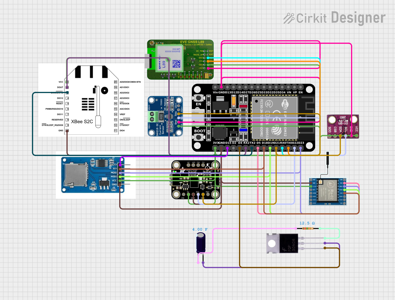


Explore Projects Built with XBee
Common Applications:
- Home automation and smart devices
- Industrial monitoring and control systems
- Wireless sensor networks
- Robotics and remote control systems
- IoT applications requiring low-power, long-range communication
Technical Specifications
The XBee S2C module is designed to provide reliable wireless communication with the following key specifications:
| Parameter | Specification |
|---|---|
| Manufacturer | Digi |
| Part Number | XBee S2C |
| Communication Standard | IEEE 802.15.4 |
| Frequency Band | 2.4 GHz |
| Data Rate | Up to 250 kbps |
| Range | Up to 120 meters indoors, 3.2 kilometers outdoors (line of sight) |
| Supply Voltage | 2.1V to 3.6V |
| Transmit Power | +3 dBm to +18 dBm |
| Receiver Sensitivity | -102 dBm |
| Operating Temperature | -40°C to +85°C |
| Antenna Options | PCB antenna, U.FL connector, or RF pad |
| Network Topologies | Point-to-point, point-to-multipoint, and mesh |
| Power Consumption (TX) | 31 mA (typical) |
| Power Consumption (RX) | 29 mA (typical) |
Pin Configuration and Descriptions
The XBee S2C module has a 20-pin configuration. Below is a table describing the pin functions:
| Pin Number | Pin Name | Description |
|---|---|---|
| 1 | VCC | Power supply input (2.1V to 3.6V) |
| 2 | DOUT | UART Data Out |
| 3 | DIN/CONFIG | UART Data In / Configuration input |
| 4 | DIO12 | Digital I/O 12 |
| 5 | RESET | Reset input (active low) |
| 6 | RSSI | Signal strength indicator (PWM output) |
| 7 | DIO10/PWM0 | Digital I/O 10 / PWM output 0 |
| 8 | DIO11/PWM1 | Digital I/O 11 / PWM output 1 |
| 9 | DIO4 | Digital I/O 4 |
| 10 | GND | Ground |
| 11 | DIO3 | Digital I/O 3 |
| 12 | DIO2 | Digital I/O 2 |
| 13 | DIO1 | Digital I/O 1 |
| 14 | DIO0/AD0 | Digital I/O 0 / Analog input 0 |
| 15 | VREF | Voltage reference for analog inputs |
| 16 | DIO6 | Digital I/O 6 |
| 17 | DIO7 | Digital I/O 7 |
| 18 | DTR/SLEEP_RQ | Sleep request input |
| 19 | DIO8 | Digital I/O 8 |
| 20 | DIO9 | Digital I/O 9 |
Usage Instructions
How to Use the XBee S2C in a Circuit
- Power Supply: Connect the VCC pin to a regulated power source (2.1V to 3.6V) and the GND pin to ground.
- UART Communication: Use the DOUT (pin 2) and DIN/CONFIG (pin 3) pins to establish UART communication with a microcontroller or PC.
- Antenna: Ensure the module is equipped with an appropriate antenna (PCB, U.FL, or RF pad) for optimal performance.
- Configuration: Use Digi's XCTU software to configure the XBee S2C module. Connect the module to a PC using an XBee USB adapter or breakout board.
- Network Setup: Configure the module as a coordinator, router, or end device depending on your network topology.
Important Considerations and Best Practices
- Voltage Levels: Ensure the module operates within the specified voltage range to avoid damage.
- Antenna Placement: Place the antenna in a location free from obstructions for maximum range and signal strength.
- Sleep Mode: Use the DTR/SLEEP_RQ pin to enable sleep mode for low-power applications.
- Firmware Updates: Regularly update the module's firmware using XCTU to access the latest features and bug fixes.
Example: Connecting XBee S2C to Arduino UNO
Below is an example of how to connect the XBee S2C to an Arduino UNO and send data wirelessly:
Wiring:
- Connect XBee's VCC to Arduino's 3.3V pin.
- Connect XBee's GND to Arduino's GND.
- Connect XBee's DOUT to Arduino's RX (pin 0).
- Connect XBee's DIN/CONFIG to Arduino's TX (pin 1).
Code:
#include <SoftwareSerial.h>

// Define RX and TX pins for SoftwareSerial
SoftwareSerial XBee(2, 3); // RX = pin 2, TX = pin 3

void setup() {
  Serial.begin(9600); // Start Serial Monitor communication
  XBee.begin(9600);   // Start XBee communication

  Serial.println("XBee S2C Communication Initialized");
}

void loop() {
  // Send data to XBee
  XBee.println("Hello from Arduino!");

  // Check if data is received from XBee
  if (XBee.available()) {
    String receivedData = XBee.readString();
    Serial.print("Received: ");
    Serial.println(receivedData);
  }

  delay(1000); // Wait 1 second before sending the next message
}
Troubleshooting and FAQs
Common Issues and Solutions
No Communication Between Modules:
- Ensure both modules are configured with the same PAN ID and baud rate.
- Verify that one module is set as the coordinator and the other as a router or end device.
Short Range or Weak Signal:
- Check the antenna connection and placement.
- Avoid physical obstructions and interference from other 2.4 GHz devices.
Module Not Detected in XCTU:
- Ensure the module is properly connected to the USB adapter or breakout board.
- Check the COM port settings in XCTU.
High Power Consumption:
- Enable sleep mode using the DTR/SLEEP_RQ pin for battery-powered applications.
FAQs
Q: Can the XBee S2C communicate with other XBee modules?
A: Yes, the XBee S2C is compatible with other XBee modules that operate on the IEEE 802.15.4 standard.
Q: How do I reset the XBee S2C to factory settings?
A: Use the XCTU software to perform a factory reset or hold the RESET pin low for a few seconds.
Q: What is the maximum number of devices in a mesh network?
A: The XBee S2C supports up to 10,000 devices in a Zigbee mesh network.
Q: Can I use the XBee S2C with a 5V microcontroller?
A: Yes, but you must use a level shifter or voltage divider to ensure the module's pins receive 3.3V signals.