How to Use Motor Encouder: Examples, Pinouts, and Specs
Introduction
The Pololu Motor Encoder (Part ID: 3081) is a device designed to convert the rotational position or motion of a motor shaft into an electrical signal. This encoder provides precise feedback, enabling accurate control of motor speed, direction, and position. It is commonly used in robotics, automation systems, and other applications requiring closed-loop motor control.
Explore Projects Built with Motor Encouder

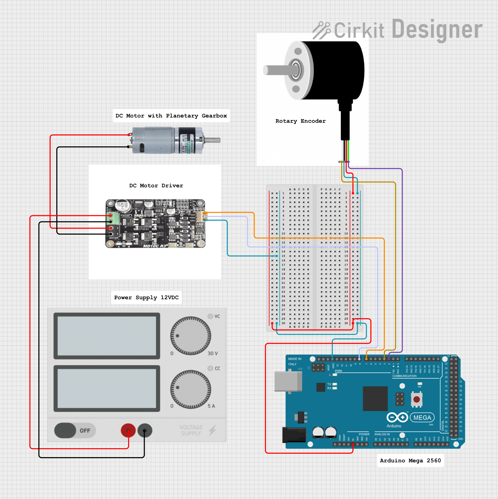
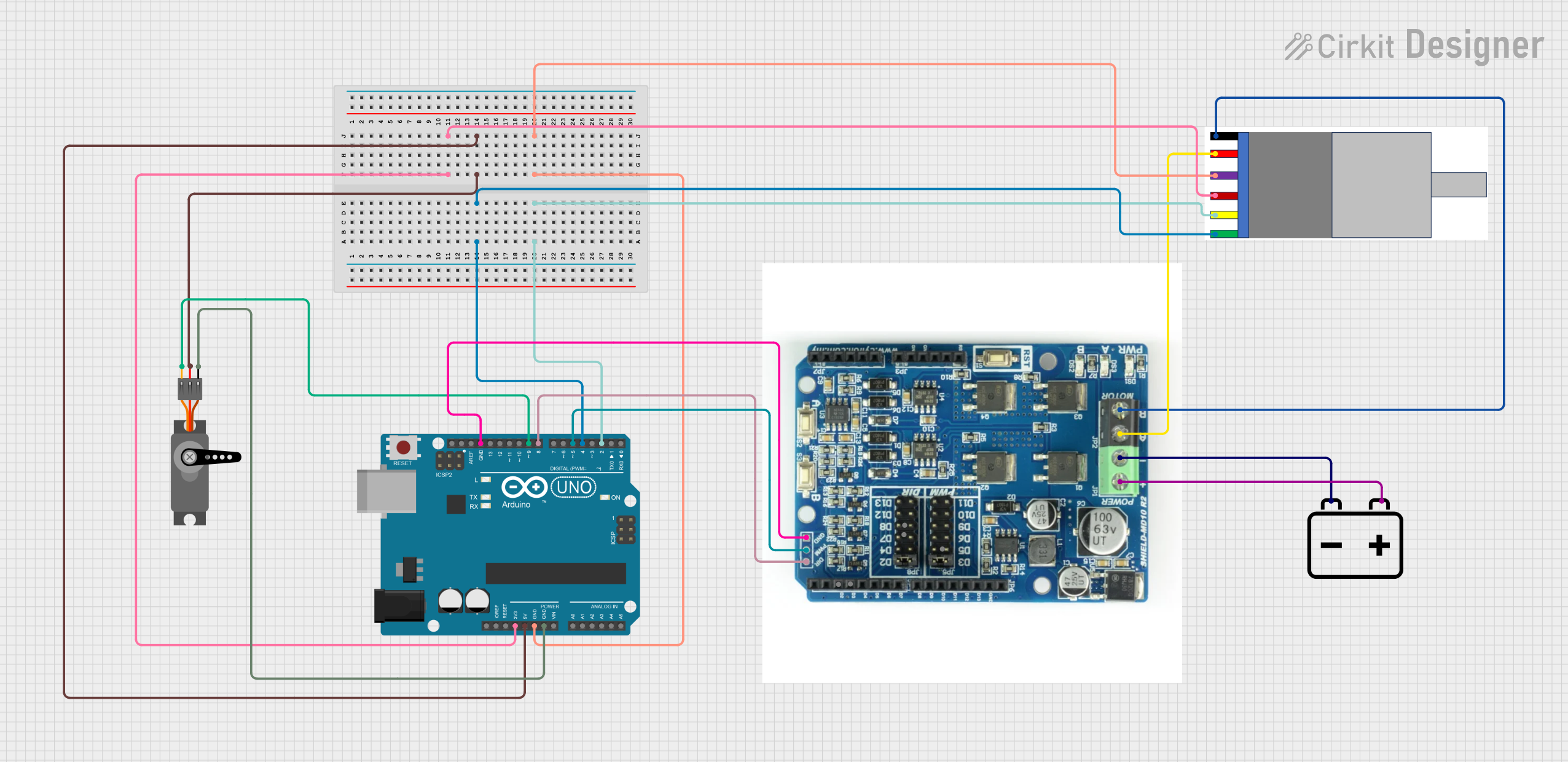
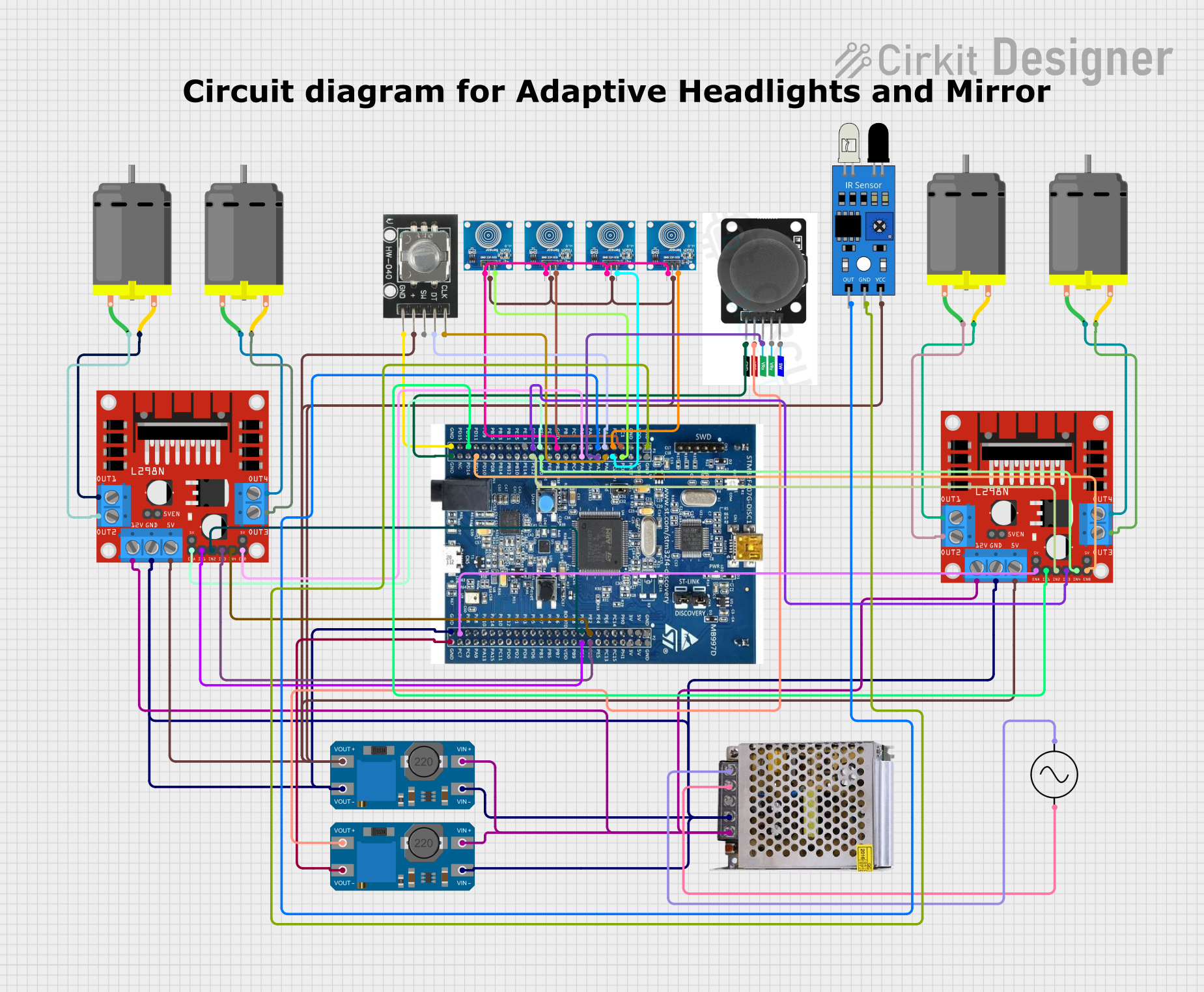
Explore Projects Built with Motor Encouder
Common Applications
- Robotics for precise motor control and navigation
- Industrial automation systems
- CNC machines and 3D printers
- Motor speed and position monitoring
- Feedback systems in servo motors
Technical Specifications
The Pololu Motor Encoder (Part ID: 3081) is designed to work with DC motors and provides quadrature output signals for precise motion tracking. Below are the key technical details:
Key Specifications
| Parameter | Value |
|---|---|
| Manufacturer | Pololu |
| Part ID | 3081 |
| Operating Voltage | 3.3 V to 5 V |
| Output Signal Type | Quadrature (A and B channels) |
| Resolution | 12 counts per revolution (CPR) |
| Maximum Motor Shaft Diameter | 3 mm |
| Operating Temperature | -40°C to 85°C |
| Dimensions | 20 mm x 15 mm x 5 mm |
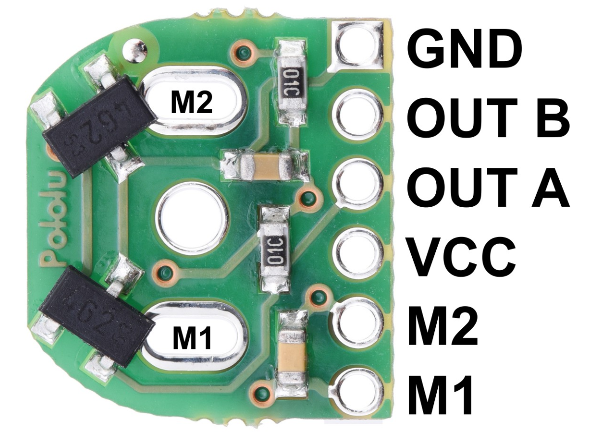
Pin Configuration
The encoder has a 5-pin interface for connecting to a microcontroller or motor driver. The pinout is as follows:
| Pin Number | Name | Description |
|---|---|---|
| 1 | VCC | Power supply input (3.3 V to 5 V) |
| 2 | GND | Ground connection |
| 3 | A | Quadrature output channel A |
| 4 | B | Quadrature output channel B |
| 5 | Index | Optional index signal for additional feedback |
Usage Instructions
How to Use the Motor Encoder in a Circuit
- Mounting the Encoder: Secure the encoder to the motor shaft using the provided mounting hardware. Ensure proper alignment to avoid signal errors.
- Wiring: Connect the encoder pins to your microcontroller or motor driver as follows:
- Connect
VCCto a 3.3 V or 5 V power source. - Connect
GNDto the ground of your circuit. - Connect
AandBto the digital input pins of your microcontroller for reading quadrature signals. - Optionally, connect the
Indexpin if your application requires it.
- Connect
- Reading Signals: Use the quadrature signals (A and B) to determine the direction and speed of the motor. The signals are 90° out of phase, allowing for precise motion tracking.
Important Considerations
- Power Supply: Ensure the encoder operates within the specified voltage range (3.3 V to 5 V).
- Signal Noise: Use pull-up resistors on the A and B channels if the signals are noisy.
- Alignment: Properly align the encoder with the motor shaft to avoid inaccurate readings.
- Debouncing: Implement software debouncing or filtering to handle signal fluctuations.
Example Code for Arduino UNO
Below is an example of how to use the Pololu Motor Encoder with an Arduino UNO to read the quadrature signals and calculate motor position:
// Define encoder pins
const int encoderPinA = 2; // Connect to encoder channel A
const int encoderPinB = 3; // Connect to encoder channel B

volatile int encoderPosition = 0; // Variable to store encoder position
int lastEncoded = 0; // Tracks the last encoder state

void setup() {
  pinMode(encoderPinA, INPUT); // Set channel A as input
  pinMode(encoderPinB, INPUT); // Set channel B as input

  // Enable pull-up resistors to reduce noise
  digitalWrite(encoderPinA, HIGH);
  digitalWrite(encoderPinB, HIGH);

  // Attach interrupts to encoder pins
  attachInterrupt(digitalPinToInterrupt(encoderPinA), updateEncoder, CHANGE);
  attachInterrupt(digitalPinToInterrupt(encoderPinB), updateEncoder, CHANGE);

  Serial.begin(9600); // Initialize serial communication
}

void loop() {
  // Print the encoder position to the serial monitor
  Serial.print("Encoder Position: ");
  Serial.println(encoderPosition);
  delay(100); // Delay for readability
}

void updateEncoder() {
  // Read the current state of the encoder pins
  int MSB = digitalRead(encoderPinA); // Most significant bit
  int LSB = digitalRead(encoderPinB); // Least significant bit

  int encoded = (MSB << 1) | LSB; // Combine the two bits
  int sum = (lastEncoded << 2) | encoded; // Track state changes

  // Update position based on state transitions
  if (sum == 0b1101 || sum == 0b0100 || sum == 0b0010 || sum == 0b1011) {
    encoderPosition++;
  } else if (sum == 0b1110 || sum == 0b0111 || sum == 0b0001 || sum == 0b1000) {
    encoderPosition--;
  }

  lastEncoded = encoded; // Update the last state
}
Notes on the Code
- The code uses interrupts to handle real-time updates of the encoder position.
- Ensure the encoder pins are connected to interrupt-capable pins on the Arduino UNO (e.g., pins 2 and 3).
- Adjust the
encoderPositionvariable as needed for your application.
Troubleshooting and FAQs
Common Issues
No Signal Detected:
- Check the wiring and ensure all connections are secure.
- Verify the power supply voltage is within the specified range (3.3 V to 5 V).
Inaccurate Readings:
- Ensure the encoder is properly aligned with the motor shaft.
- Use pull-up resistors on the A and B channels to reduce noise.
Signal Fluctuations:
- Implement software debouncing or filtering in your code.
- Check for loose connections or interference from nearby components.
Encoder Not Responding:
- Verify that the microcontroller pins are configured as inputs.
- Test the encoder with a multimeter to ensure it is functioning correctly.
FAQs
Q: Can this encoder be used with a 12 V motor?
A: Yes, the encoder can be used with a 12 V motor, but the encoder itself must be powered with 3.3 V to 5 V.
Q: How do I calculate motor speed using the encoder?
A: Measure the time between pulses on the A or B channel and use the encoder's resolution (12 CPR) to calculate speed.
Q: Can I use this encoder with a Raspberry Pi?
A: Yes, the encoder can be connected to GPIO pins on a Raspberry Pi. Use libraries like RPi.GPIO or pigpio to read the quadrature signals.
Q: What is the purpose of the Index pin?
A: The Index pin provides a reference signal for applications requiring absolute position tracking. It is optional and not always needed.
By following this documentation, you can effectively integrate the Pololu Motor Encoder (Part ID: 3081) into your projects for precise motor control and feedback.