How to Use MAX6675 edit: Examples, Pinouts, and Specs
Introduction
The MAX6675 is a digital temperature sensor designed to interface with K-type thermocouples, providing accurate temperature readings in the range of 0°C to 1024°C. It features a built-in 12-bit analog-to-digital converter (ADC) and communicates with microcontrollers via the SPI (Serial Peripheral Interface) protocol. The MAX6675 is widely used in applications requiring precise temperature monitoring, such as industrial automation, HVAC systems, and laboratory equipment.
Explore Projects Built with MAX6675 edit


Explore Projects Built with MAX6675 edit
Technical Specifications
- Temperature Range: 0°C to 1024°C
- Resolution: 0.25°C
- Accuracy: ±2°C (typical)
- Supply Voltage: 3.0V to 5.5V
- Current Consumption: 1.5mA (typical)
- Communication Protocol: SPI
- Thermocouple Type: K-type
- Conversion Time: 0.22 seconds (typical)
- Operating Temperature: -20°C to +85°C (for the IC)
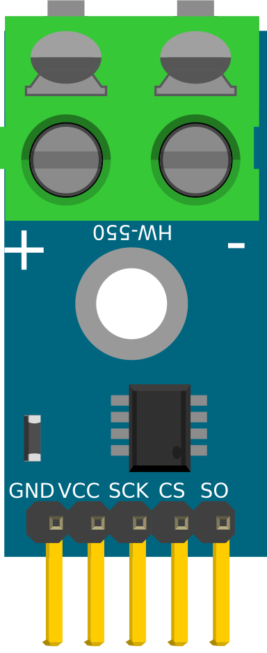
Pin Configuration and Descriptions
The MAX6675 is typically available in an 8-pin SOIC package. Below is the pinout and description:
| Pin Number | Pin Name | Description |
|---|---|---|
| 1 | SO | Serial data output (SPI interface). Sends temperature data to the microcontroller. |
| 2 | CS | Chip Select. Active low; enables communication with the MAX6675. |
| 3 | CLK | Serial clock input (SPI interface). Used to synchronize data transfer. |
| 4 | GND | Ground. Connect to the system ground. |
| 5 | VCC | Power supply. Connect to a 3.0V to 5.5V source. |
| 6 | T- | Negative terminal of the K-type thermocouple. |
| 7 | T+ | Positive terminal of the K-type thermocouple. |
| 8 | NC | No connection. Leave unconnected. |
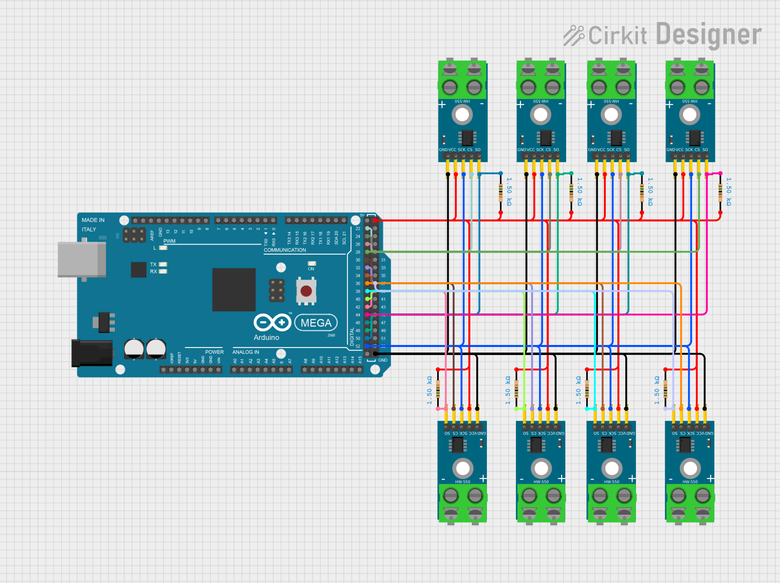
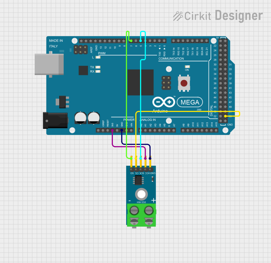
Usage Instructions
How to Use the MAX6675 in a Circuit
- Power Supply: Connect the VCC pin to a 3.0V to 5.5V power source and the GND pin to the system ground.
- Thermocouple Connection: Attach the K-type thermocouple to the T+ and T- pins. Ensure proper polarity.
- SPI Communication:
- Connect the SO pin to the MISO (Master In Slave Out) pin of the microcontroller.
- Connect the CS pin to a digital output pin on the microcontroller. This pin will be used to enable/disable communication.
- Connect the CLK pin to the SPI clock pin of the microcontroller.
- Microcontroller Configuration: Configure the microcontroller to use SPI communication with the MAX6675. The SPI mode should be set to Mode 0 (CPOL = 0, CPHA = 0).
Important Considerations and Best Practices
- Thermocouple Placement: Ensure the thermocouple is securely attached to the measurement point for accurate readings.
- Noise Reduction: Use short, shielded wires for the thermocouple to minimize noise interference.
- Cold-Junction Compensation: The MAX6675 includes built-in cold-junction compensation, so no external compensation is required.
- SPI Timing: Ensure the SPI clock frequency does not exceed 4.3MHz for reliable communication.
- Thermocouple Type: Only use K-type thermocouples with the MAX6675.
Example Code for Arduino UNO
Below is an example of how to interface the MAX6675 with an Arduino UNO to read temperature data:
#include <SPI.h>

// Define MAX6675 pins
const int CS_PIN = 10; // Chip Select pin
const int CLK_PIN = 13; // SPI Clock pin
const int SO_PIN = 12;  // Serial Output pin

void setup() {
  Serial.begin(9600); // Initialize serial communication
  pinMode(CS_PIN, OUTPUT); // Set CS pin as output
  digitalWrite(CS_PIN, HIGH); // Set CS pin high (inactive)
  SPI.begin(); // Initialize SPI communication
}

float readTemperature() {
  uint16_t value = 0;

  // Start communication with MAX6675
  digitalWrite(CS_PIN, LOW);
  delayMicroseconds(1);

  // Read 16 bits of data from the MAX6675
  value = SPI.transfer(0x00) << 8; // Read high byte
  value |= SPI.transfer(0x00);    // Read low byte

  digitalWrite(CS_PIN, HIGH); // End communication

  // Check for thermocouple connection error
  if (value & 0x0004) {
    return NAN; // Return NaN if no thermocouple is connected
  }

  // Extract temperature data (bits 3 to 15) and convert to Celsius
  value >>= 3; // Shift right to remove unused bits
  return value * 0.25; // Multiply by resolution (0.25°C per bit)
}

void loop() {
  float temperature = readTemperature(); // Read temperature
  if (isnan(temperature)) {
    Serial.println("Thermocouple not connected!");
  } else {
    Serial.print("Temperature: ");
    Serial.print(temperature);
    Serial.println(" °C");
  }
  delay(1000); // Wait 1 second before next reading
}
Troubleshooting and FAQs
Common Issues and Solutions
No Temperature Reading:
- Cause: Thermocouple not connected or improperly connected.
- Solution: Verify the thermocouple is securely connected to the T+ and T- pins.
Incorrect Temperature Values:
- Cause: Noise interference or incorrect thermocouple type.
- Solution: Use shielded wires for the thermocouple and ensure a K-type thermocouple is used.
SPI Communication Fails:
- Cause: Incorrect SPI configuration or wiring.
- Solution: Verify the SPI mode is set to Mode 0 and check all connections.
Thermocouple Error Flag:
- Cause: Open thermocouple or damaged sensor.
- Solution: Check the thermocouple for continuity and replace if necessary.
FAQs
Q: Can the MAX6675 measure negative temperatures?
A: No, the MAX6675 is designed to measure temperatures from 0°C to 1024°C only.Q: Can I use a different type of thermocouple with the MAX6675?
A: No, the MAX6675 is specifically designed for K-type thermocouples.Q: What is the maximum SPI clock frequency for the MAX6675?
A: The maximum SPI clock frequency is 4.3MHz.Q: Does the MAX6675 require external cold-junction compensation?
A: No, the MAX6675 includes built-in cold-junction compensation.