The EverSet ES100 WWVB BPSK Atomic Clock Starter Kit is a precision timekeeping module designed to synchronize with the WWVB time signal broadcast by NIST in Fort Collins, Colorado. Utilizing advanced Binary Phase-Shift Keying (BPSK) modulation, this kit ensures highly accurate time synchronization for a wide range of applications, including industrial systems, IoT devices, and consumer electronics.
This starter kit is ideal for developers and hobbyists looking to integrate atomic clock precision into their projects. It simplifies the process of receiving and decoding WWVB signals, making it an excellent choice for applications requiring reliable and accurate timekeeping.
Explore Projects Built with EverSet ES100 WWVB BPSK Atomic Clock Starter Kit
Use Cirkit Designer to design, explore, and prototype these projects online. Some projects support real-time simulation. Click "Open Project" to start designing instantly!
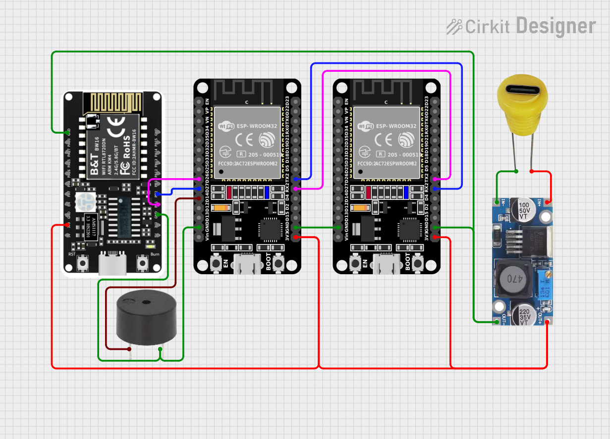
This circuit features two ESP32 microcontrollers configured to communicate with each other via serial connection, as indicated by the cross-connection of their TX2 and RX2 pins. A BW16-Kit-1 microcontroller is also included, interfacing with one of the ESP32s through pins D26 and D27. Power is supplied to the microcontrollers through a step-down buck converter connected to a 5V Type C DC socket, and a buzzer is driven by one of the ESP32s, potentially for audio signaling purposes.
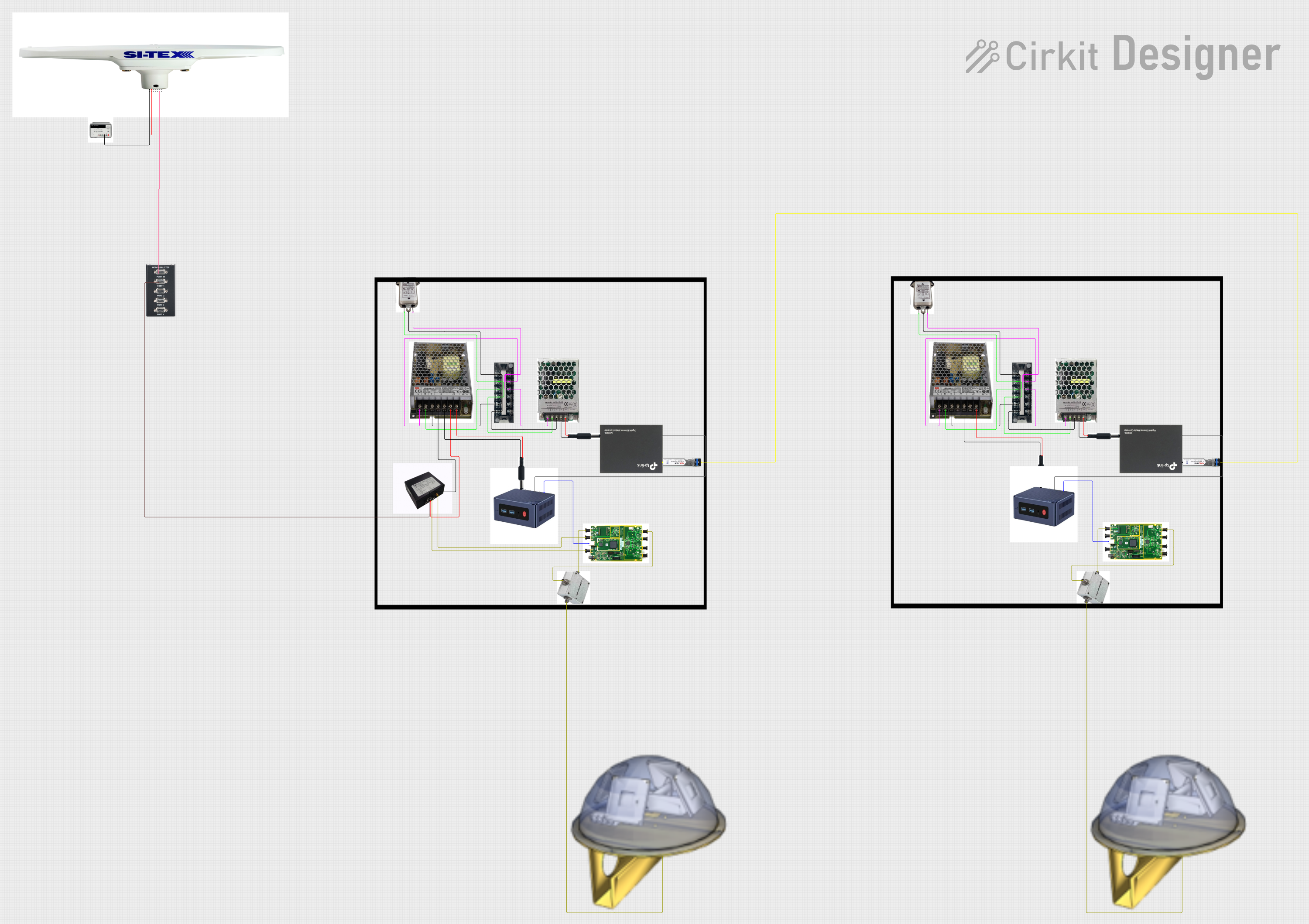
This circuit appears to be a complex system involving power supply management, GPS and timing synchronization, and data communication. It includes a SI-TEX G1 Satellite Compass for GPS data, an XHTF1021 Atomic Rubidium Clock for precise timing, and Ettus USRP B200 units for software-defined radio communication. Power is supplied through various SMPS units and distributed via terminal blocks and DC jacks. Data communication is facilitated by Beelink MINI S12 N95 computers, RS232 splitters, and a 1000BASE-T Media Converter for network connectivity. RF Directional Couplers are used to interface antennas with the USRP units, and the entire system is likely contained within cases for protection and organization.
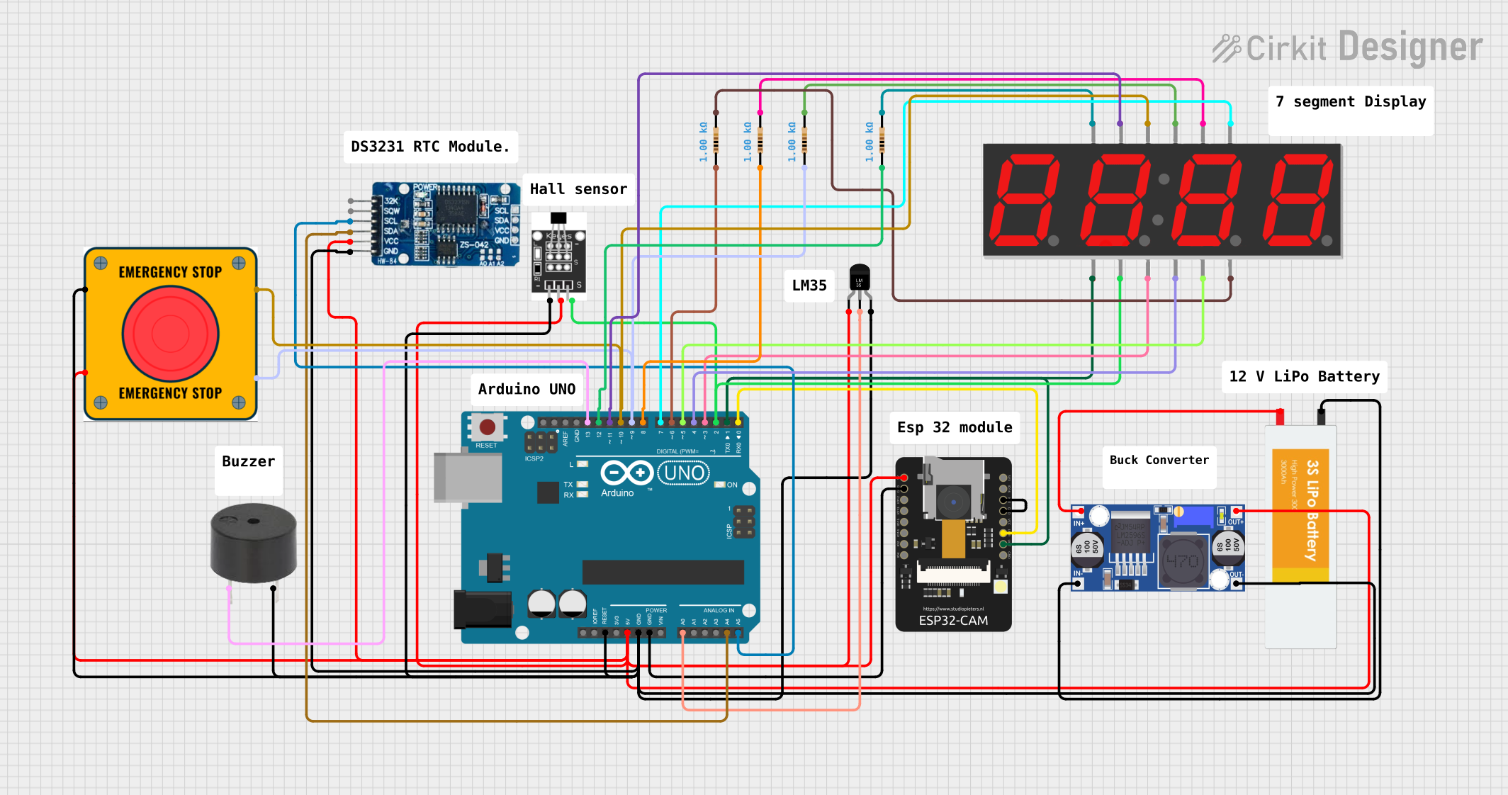
This is a multi-functional embedded system featuring temperature monitoring, timekeeping, visual display, potential Wi-Fi/camera capabilities, magnetic field detection, and power management with emergency stop functionality. It is designed around an Arduino UNO and an ESP32-CAM, with a buck converter for power regulation from a LiPo battery.
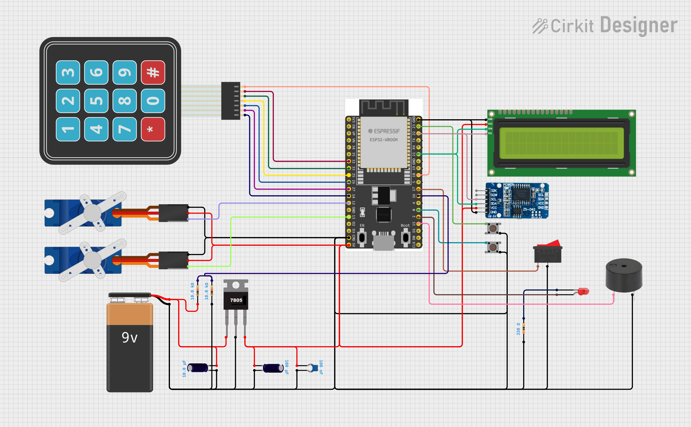
This circuit features an ESP32 microcontroller interfaced with a membrane matrix keypad, an I2C LCD screen, a real-time clock (RTC DS3231), two servos, a buzzer, and additional components like resistors and capacitors for stabilization and current limiting. The ESP32 runs embedded code to manage a keypad-based user interface, display information on the LCD, and control alarms and servo positions based on the RTC input, likely for a timed locking/unlocking mechanism or scheduled alert system. The circuit includes a WiFi setup for remote connectivity and EEPROM for non-volatile storage of configurations and schedules.
Precision timekeeping in industrial and scientific equipment
Synchronization of IoT devices and networks
Consumer electronics such as clocks and watches
Data logging systems requiring accurate timestamps
Educational projects and prototyping
Technical Specifications
Key Technical Details
Parameter
Specification
Manufacturer
EverSet
Part ID
ES100
Signal Type
WWVB (60 kHz) with BPSK modulation
Operating Voltage
2.2V to 3.6V
Current Consumption
100 µA (typical during reception)
Operating Temperature
-40°C to +85°C
Time Accuracy
±100 microseconds (synchronized)
Communication Interface
UART (9600 baud rate)
Dimensions
25 mm x 25 mm x 5 mm
Pin Configuration and Descriptions
The ES100 module has a 6-pin interface for power, communication, and control. Below is the pinout:
Pin Number
Pin Name
Description
1
VCC
Power supply input (2.2V to 3.6V)
2
GND
Ground
3
RX
UART receive pin (connect to host TX)
4
TX
UART transmit pin (connect to host RX)
5
EN
Enable pin (active high)
6
NC
Not connected (leave unconnected)
Usage Instructions
How to Use the Component in a Circuit
Power Supply: Connect the VCC pin to a regulated 3.3V power source and the GND pin to ground.
UART Communication: Connect the RX pin of the ES100 to the TX pin of your microcontroller and the TX pin of the ES100 to the RX pin of your microcontroller.
Enable Pin: Pull the EN pin high (3.3V) to activate the module. When not in use, pull the EN pin low to conserve power.
Antenna Placement: Ensure the module's antenna is placed in an open area, away from sources of interference, to receive the WWVB signal effectively.
Important Considerations and Best Practices
Signal Reception: The WWVB signal is strongest at night. For optimal performance, test the module during nighttime hours.
Antenna Orientation: Position the antenna perpendicular to the direction of the WWVB transmitter in Fort Collins, Colorado.
Power Supply Noise: Use a low-noise power supply to avoid interference with the WWVB signal.
UART Configuration: Set the UART baud rate to 9600, 8 data bits, no parity, and 1 stop bit (8N1).
Example Code for Arduino UNO
Below is an example of how to interface the ES100 module with an Arduino UNO to receive time data:
#include <SoftwareSerial.h>

// Define RX and TX pins for SoftwareSerial
SoftwareSerial es100Serial(10, 11); // RX = Pin 10, TX = Pin 11

void setup() {
  Serial.begin(9600); // Initialize Serial Monitor
  es100Serial.begin(9600); // Initialize ES100 communication

  pinMode(9, OUTPUT); // Pin 9 for EN (Enable)
  digitalWrite(9, HIGH); // Enable the ES100 module

  Serial.println("ES100 WWVB Atomic Clock Module Initialized");
}

void loop() {
  // Request time data from the ES100 module
  es100Serial.write("T"); // Send 'T' command to request time

  // Wait for a response
  if (es100Serial.available()) {
    String timeData = "";
    while (es100Serial.available()) {
      char c = es100Serial.read();
      timeData += c;
    }

    // Print the received time data to the Serial Monitor
    Serial.println("Received Time Data: " + timeData);
  }

  delay(60000); // Wait 1 minute before requesting time again
}
Troubleshooting and FAQs
Common Issues and Solutions
No Signal Reception:
Ensure the antenna is properly connected and positioned.
Test the module during nighttime for better signal strength.
Verify that the power supply is stable and noise-free.
Incorrect Time Data:
Check the UART connections and ensure the baud rate is set to 9600.
Confirm that the EN pin is pulled high to activate the module.
Module Not Responding:
Verify the power supply voltage (2.2V to 3.6V).
Ensure the EN pin is not left floating; it must be actively driven high or low.
FAQs
Q: Can the ES100 module work indoors?
A: Yes, but signal reception may be weaker indoors. Place the antenna near a window or in an open area for better results.
Q: What is the maximum distance from the WWVB transmitter for reliable operation?
A: The WWVB signal can be received across most of North America, but reception quality depends on environmental factors and interference.
Q: Can I use the ES100 module with a 5V microcontroller?
A: Yes, but you must use a level shifter to step down the 5V logic levels to 3.3V for the ES100 module.
Q: How often should I request time data?
A: It is recommended to request time data once every minute or as needed for your application.
This documentation provides a comprehensive guide to using the EverSet ES100 WWVB BPSK Atomic Clock Starter Kit. For further assistance, refer to the manufacturer's datasheet or contact EverSet support.


 Open Project in Cirkit Designer