How to Use BEC module : Examples, Pinouts, and Specs
Introduction
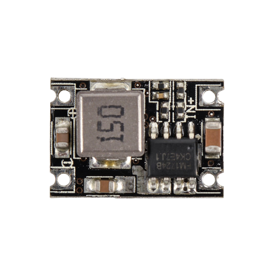
A BEC (Battery Eliminator Circuit) module is an electronic device designed to provide a stable, regulated voltage output from a higher voltage input source. It is commonly used in remote-controlled (RC) vehicles, drones, and other electronic systems to power components such as servos, receivers, and flight controllers without requiring a separate battery. By stepping down the voltage from the main power source (e.g., LiPo battery), the BEC module ensures that sensitive electronics receive a consistent and safe voltage level.
Explore Projects Built with BEC module


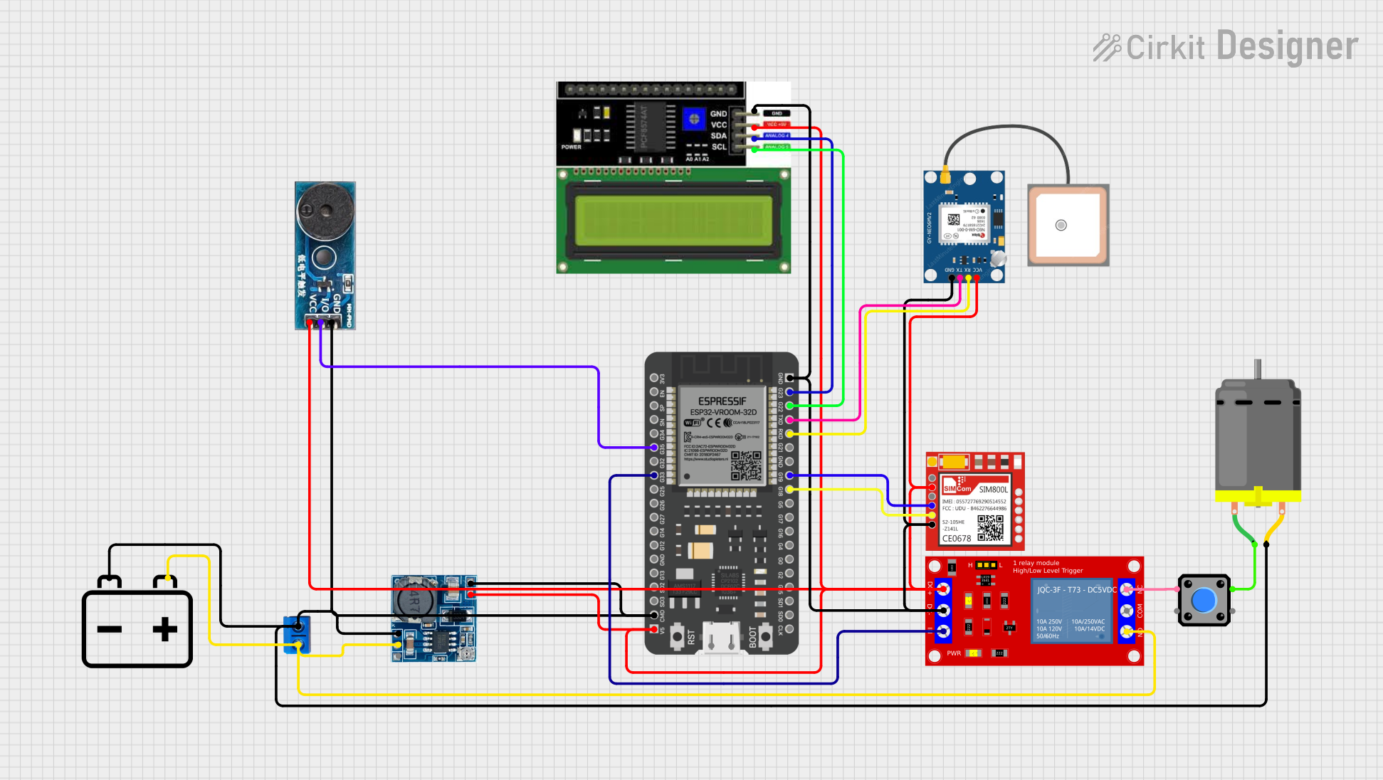
Explore Projects Built with BEC module
Common Applications and Use Cases
- Powering RC vehicle receivers and servos
- Supplying voltage to flight controllers in drones
- Providing regulated power to LEDs or other low-voltage components
- Eliminating the need for multiple batteries in electronic systems
Technical Specifications
Below are the typical technical specifications for a standard BEC module. Note that actual values may vary depending on the specific model.
| Parameter | Specification |
|---|---|
| Input Voltage Range | 6V to 26V (2S to 6S LiPo batteries) |
| Output Voltage Options | 5V or 6V (selectable on some models) |
| Maximum Output Current | 3A to 5A (depending on the model) |
| Efficiency | Up to 90% |
| Output Voltage Ripple | <50mV |
| Operating Temperature | -20°C to 85°C |
| Dimensions | Typically 25mm x 15mm x 8mm |
| Weight | ~10g |
Pin Configuration and Descriptions
The BEC module typically has three main connections: input, output, and ground. Below is a table describing the pin configuration.
| Pin Name | Description |
|---|---|
| VIN (+) | Positive input voltage from the battery source |
| GND | Ground connection (common for input and output) |
| VOUT (+) | Regulated output voltage to power the load |
Some BEC modules may also include a jumper or switch to select the output voltage (e.g., 5V or 6V).
Usage Instructions
How to Use the BEC Module in a Circuit
Connect the Input Voltage:
- Connect the VIN (+) pin to the positive terminal of your battery or power source.
- Connect the GND pin to the negative terminal of your battery or power source.
Connect the Output Voltage:
- Connect the VOUT (+) pin to the positive terminal of the device you want to power (e.g., receiver, servo, or flight controller).
- Connect the GND pin to the ground terminal of the device.
Voltage Selection (if applicable):
- If your BEC module has a voltage selection jumper or switch, set it to the desired output voltage (e.g., 5V or 6V) before powering the module.
Power On:
- Once all connections are secure, power on the system. The BEC module will regulate the input voltage and provide a stable output to your connected devices.
Important Considerations and Best Practices
- Check Voltage Ratings: Ensure that the input voltage is within the specified range of the BEC module. Exceeding the maximum input voltage can damage the module.
- Avoid Overloading: Do not exceed the maximum output current rating of the BEC module. Overloading can cause overheating or failure.
- Heat Dissipation: If the BEC module becomes warm during operation, ensure proper ventilation or consider adding a heatsink to improve heat dissipation.
- Polarity: Double-check the polarity of all connections to avoid damaging the module or connected devices.
- Noise Filtering: For sensitive applications, consider adding a capacitor on the output to further reduce voltage ripple.
Example: Using a BEC Module with an Arduino UNO
A BEC module can be used to power an Arduino UNO from a higher voltage source, such as a 3S LiPo battery (11.1V). Below is an example connection and code.
Wiring Diagram
- Connect the VIN (+) pin of the BEC module to the positive terminal of the LiPo battery.
- Connect the GND pin of the BEC module to the negative terminal of the LiPo battery.
- Connect the VOUT (+) pin of the BEC module to the 5V pin of the Arduino UNO.
- Connect the GND pin of the BEC module to the GND pin of the Arduino UNO.
Example Code
// Example code to blink an LED connected to pin 13 of the Arduino UNO
// Ensure the Arduino is powered via the BEC module (5V output)

void setup() {
  pinMode(13, OUTPUT); // Set pin 13 as an output
}

void loop() {
  digitalWrite(13, HIGH); // Turn the LED on
  delay(1000);            // Wait for 1 second
  digitalWrite(13, LOW);  // Turn the LED off
  delay(1000);            // Wait for 1 second
}
Troubleshooting and FAQs
Common Issues and Solutions
BEC Module Not Powering the Load:
- Cause: Incorrect wiring or polarity.
- Solution: Double-check all connections and ensure the input and output polarities are correct.
Overheating:
- Cause: Exceeding the maximum current rating or poor ventilation.
- Solution: Reduce the load current or improve airflow around the module. Consider using a heatsink.
Voltage Output is Unstable:
- Cause: Input voltage is too low or noisy.
- Solution: Ensure the input voltage is within the specified range. Add a capacitor to the input or output for additional filtering.
No Output Voltage:
- Cause: Faulty module or blown internal components.
- Solution: Test the module with a multimeter. Replace the module if it is damaged.
FAQs
Q: Can I use a BEC module with a 4S LiPo battery?
A: Yes, as long as the input voltage of the BEC module supports the voltage range of the 4S LiPo battery (typically ~14.8V).
Q: Can I power multiple devices with a single BEC module?
A: Yes, but ensure the total current draw of all devices does not exceed the maximum output current rating of the BEC module.
Q: Is it safe to use a BEC module with sensitive electronics?
A: Yes, most BEC modules provide a stable and low-ripple output voltage, making them suitable for sensitive electronics. However, adding a capacitor for additional filtering is recommended in critical applications.
Q: How do I select the correct BEC module for my application?
A: Consider the input voltage range, output voltage, and maximum output current required for your application. Choose a module that meets or exceeds these requirements.