How to Use DC DC High Power Adjustable Booster Regulator Module: Examples, Pinouts, and Specs
Introduction
The DC DC High Power Adjustable Booster Regulator Module (Manufacturer: XINGYHENG, Part ID: XLX-230) is a versatile electronic component designed to step up a lower DC voltage to a higher DC voltage. This module is particularly useful in applications where a stable, adjustable high voltage is required from a lower voltage source. It is widely used in battery-powered devices, LED drivers, solar power systems, and other high-power applications.
Explore Projects Built with DC DC High Power Adjustable Booster Regulator Module


Explore Projects Built with DC DC High Power Adjustable Booster Regulator Module
Common Applications and Use Cases
- Powering high-voltage devices from low-voltage batteries
- LED lighting systems requiring adjustable brightness
- Solar panel voltage regulation
- DIY electronics projects
- Laboratory power supplies
Technical Specifications
The following table outlines the key technical details of the XLX-230 module:
| Parameter | Value |
|---|---|
| Input Voltage Range | 8V to 60V DC |
| Output Voltage Range | 10V to 120V DC (adjustable) |
| Maximum Output Current | 10A (depends on input voltage) |
| Maximum Output Power | 600W |
| Efficiency | Up to 95% (depending on load) |
| Operating Temperature | -40°C to +85°C |
| Dimensions | 70mm x 40mm x 30mm |
| Weight | 80g |
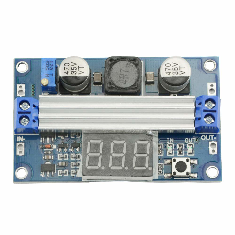
Pin Configuration and Descriptions
The XLX-230 module has the following input and output connections:
| Pin Name | Description |
|---|---|
| VIN+ | Positive input voltage terminal |
| VIN- | Negative input voltage terminal (GND) |
| VOUT+ | Positive output voltage terminal |
| VOUT- | Negative output voltage terminal (GND) |
| ADJ | Potentiometer for adjusting output voltage |
Usage Instructions
How to Use the Component in a Circuit
Connect the Input Voltage:
- Attach the positive terminal of your DC power source to the
VIN+pin. - Connect the negative terminal of your DC power source to the
VIN-pin. - Ensure the input voltage is within the range of 8V to 60V DC.
- Attach the positive terminal of your DC power source to the
Connect the Load:
- Attach the positive terminal of your load to the
VOUT+pin. - Connect the negative terminal of your load to the
VOUT-pin.
- Attach the positive terminal of your load to the
Adjust the Output Voltage:
- Use the onboard potentiometer labeled
ADJto set the desired output voltage. - Turn the potentiometer clockwise to increase the output voltage and counterclockwise to decrease it.
- Use a multimeter to measure the output voltage for precise adjustment.
- Use the onboard potentiometer labeled
Power On:
- Once all connections are secure, power on the input source.
- Verify the output voltage and ensure it matches your requirements before connecting sensitive devices.
Important Considerations and Best Practices
- Heat Dissipation: The module can generate significant heat during operation, especially at high power levels. Use a heatsink or active cooling to prevent overheating.
- Input Voltage: Ensure the input voltage is within the specified range to avoid damaging the module.
- Output Current: Do not exceed the maximum output current of 10A. Use a fuse for added protection.
- Polarity: Double-check the polarity of all connections to prevent damage to the module or connected devices.
- Load Testing: Test the module with a dummy load before connecting sensitive equipment.
Example: Using the XLX-230 with an Arduino UNO
The XLX-230 can be used to power an Arduino UNO from a low-voltage battery. Below is an example of how to connect the module and adjust the output voltage to 9V for the Arduino:
- Connect a 12V battery to the
VIN+andVIN-pins of the XLX-230. - Adjust the output voltage to 9V using the
ADJpotentiometer. - Connect the
VOUT+andVOUT-pins to the Arduino's power input (barrel jack or VIN pin).
Here is a simple Arduino sketch to blink an LED, powered by the XLX-230:
// Simple LED Blink Example
// Ensure the XLX-230 output is set to 9V before powering the Arduino UNO.

const int ledPin = 13; // Pin connected to the onboard LED

void setup() {
  pinMode(ledPin, OUTPUT); // Set the LED pin as an output
}

void loop() {
  digitalWrite(ledPin, HIGH); // Turn the LED on
  delay(1000);                // Wait for 1 second
  digitalWrite(ledPin, LOW);  // Turn the LED off
  delay(1000);                // Wait for 1 second
}
Troubleshooting and FAQs
Common Issues and Solutions
No Output Voltage:
- Check the input voltage and ensure it is within the specified range.
- Verify all connections and ensure proper polarity.
- Inspect the potentiometer and adjust it to ensure the output voltage is not set too low.
Overheating:
- Ensure adequate cooling with a heatsink or fan.
- Reduce the load current if it exceeds the module's capacity.
Fluctuating Output Voltage:
- Check the input power source for stability.
- Ensure the load is not drawing more current than the module can supply.
Module Not Working After Connection:
- Inspect for reversed polarity or short circuits.
- Replace the module if it has been damaged due to incorrect usage.
FAQs
Q: Can the XLX-230 be used with a solar panel?
A: Yes, the module is suitable for use with solar panels. Ensure the panel's output voltage is within the module's input range (8V to 60V DC).
Q: How do I calculate the maximum output current?
A: The maximum output current depends on the input voltage and power. Use the formula:
[
I_{out} = \frac{P_{max}}{V_{out}}
]
where ( P_{max} ) is 600W and ( V_{out} ) is the output voltage.
Q: Can I use the XLX-230 to charge batteries?
A: Yes, but ensure the output voltage is set to the appropriate charging voltage for the battery type, and use a current-limiting circuit if necessary.
Q: Is the module waterproof?
A: No, the XLX-230 is not waterproof. Use it in a dry environment or enclose it in a waterproof case for outdoor applications.