How to Use ESP8266 ESP-01 WiFi Module: Examples, Pinouts, and Specs
Introduction
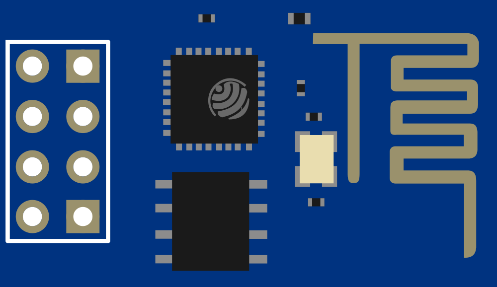
The ESP8266 ESP-01 WiFi Module is a self-contained SOC with integrated TCP/IP protocol stack that can give any microcontroller access to your WiFi network. It is capable of either hosting an application or offloading all Wi-Fi networking functions from another application processor. With its compact size and comprehensive feature set, the ESP8266 ESP-01 is a versatile component that enables rapid deployment of IoT solutions.
Explore Projects Built with ESP8266 ESP-01 WiFi Module

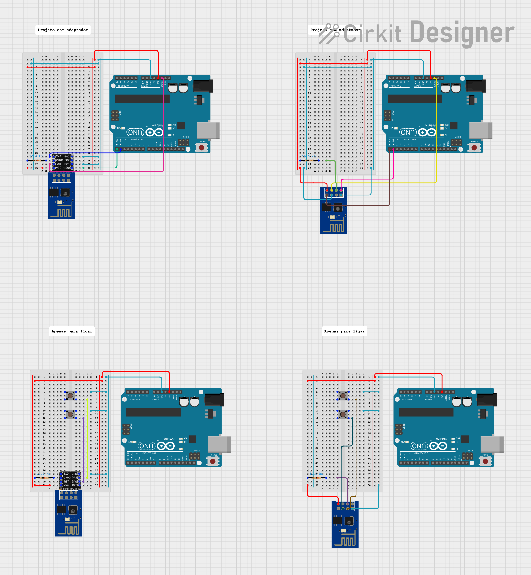
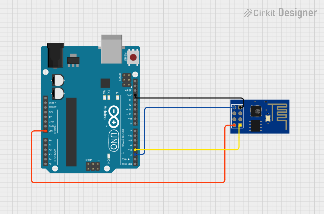

Explore Projects Built with ESP8266 ESP-01 WiFi Module
Common Applications and Use Cases
- Smart home devices
- Wireless sensor networks
- IoT applications
- Remote control of devices over the Internet
- WiFi network scanning and monitoring
Technical Specifications
Key Technical Details
- Operating Voltage: 3.3V
- Digital I/O Voltage: 3.3V (5V tolerant inputs)
- Current Consumption: ~70mA (average)
- Wireless Standard: 802.11 b/g/n
- Frequency Range: 2.4 GHz - 2.5 GHz
- Serial/UART baud rate: 115200 bps (default)
Pin Configuration and Descriptions
| Pin Number | Name | Description |
|---|---|---|
| 1 | GND | Ground |
| 2 | GPIO2 | General Purpose I/O 2 |
| 3 | GPIO0 | General Purpose I/O 0 |
| 4 | RX | UART Receive Pin |
| 5 | TX | UART Transmit Pin |
| 6 | CH_PD | Chip Power-down Pin. Active high. |
| 7 | RST | Reset Pin. Active low. |
| 8 | VCC | 3.3V Power Supply |
Usage Instructions
How to Use the Component in a Circuit
- Power Supply: Connect the VCC pin to a 3.3V supply and GND to ground. Do not power the ESP-01 with 5V, as it may damage the module.
- Serial Communication: Connect the RX and TX pins to your microcontroller's TX and RX pins, respectively. Remember that the ESP-01 operates at 3.3V logic levels.
- Programming Mode: To program the ESP-01, GPIO0 must be grounded during power-up. This puts the module into programming mode.
- Normal Operation: For normal operation, GPIO0 should be high (connected to VCC).
- Reset: The RST pin can be used to reset the module. It is active low, so pulling it to ground will reset the module.
Important Considerations and Best Practices
- Always use a stable 3.3V power supply capable of delivering sufficient current (up to 300mA during WiFi transmission bursts).
- Use a logic level converter if interfacing with 5V logic microcontrollers.
- Ensure that the antenna area is clear of metal components to avoid interference with the WiFi signal.
- For reliable operation, it is recommended to use an external antenna if the module is placed in an enclosure or in an environment with poor WiFi signal strength.
Example Code for Arduino UNO
#include <ESP8266WiFi.h>

// Replace with your network credentials
const char* ssid = "yourSSID";
const char* password = "yourPASSWORD";

void setup() {
  Serial.begin(115200); // Start the Serial communication to send messages to the computer
  delay(10);
  Serial.println('\n');

  WiFi.begin(ssid, password); // Connect to the network
  Serial.print("Connecting to ");
  Serial.print(ssid); Serial.println(" ...");

  int i = 0;
  while (WiFi.status() != WL_CONNECTED) { // Wait for the Wi-Fi to connect
    delay(1000);
    Serial.print(++i); Serial.print(' ');
  }

  Serial.println('\n');
  Serial.println("Connection established!");
  Serial.print("IP address:\t");
  Serial.println(WiFi.localIP()); // Send the IP address of the ESP8266 to the computer
}

void loop() { /* Nothing to do here */ }
Troubleshooting and FAQs
Common Issues Users Might Face
- Module not responding: Ensure that the power supply is stable and that the RX and TX connections are correct.
- Cannot connect to WiFi: Verify that the SSID and password are correct and that the WiFi signal is strong enough.
- Unexpected resets: Make sure that the CH_PD pin is connected to VCC to avoid unwanted power-downs.
Solutions and Tips for Troubleshooting
- If the module is not booting, check the power supply and the CH_PD pin connection.
- For serial communication issues, ensure that the baud rate of the ESP-01 matches that of the microcontroller's serial port.
- Use external antennas if the WiFi signal strength is weak.
- Always ensure that GPIO0 is set to the correct state for normal operation or for programming.
FAQs
Q: Can I power the ESP-01 with 5V? A: No, you must use a 3.3V power supply.
Q: How do I put the ESP-01 into programming mode? A: Ground GPIO0 and reset the module by pulling RST to ground momentarily.
Q: Can I use the ESP-01 with a 5V microcontroller like an Arduino UNO? A: Yes, but you will need a logic level converter for the RX and TX pins.
Q: How can I extend the range of the ESP-01? A: Use an external antenna and ensure that the antenna area is free from obstructions and interference.