How to Use 2N/O 25A 230V AC Contactor: Examples, Pinouts, and Specs
Introduction
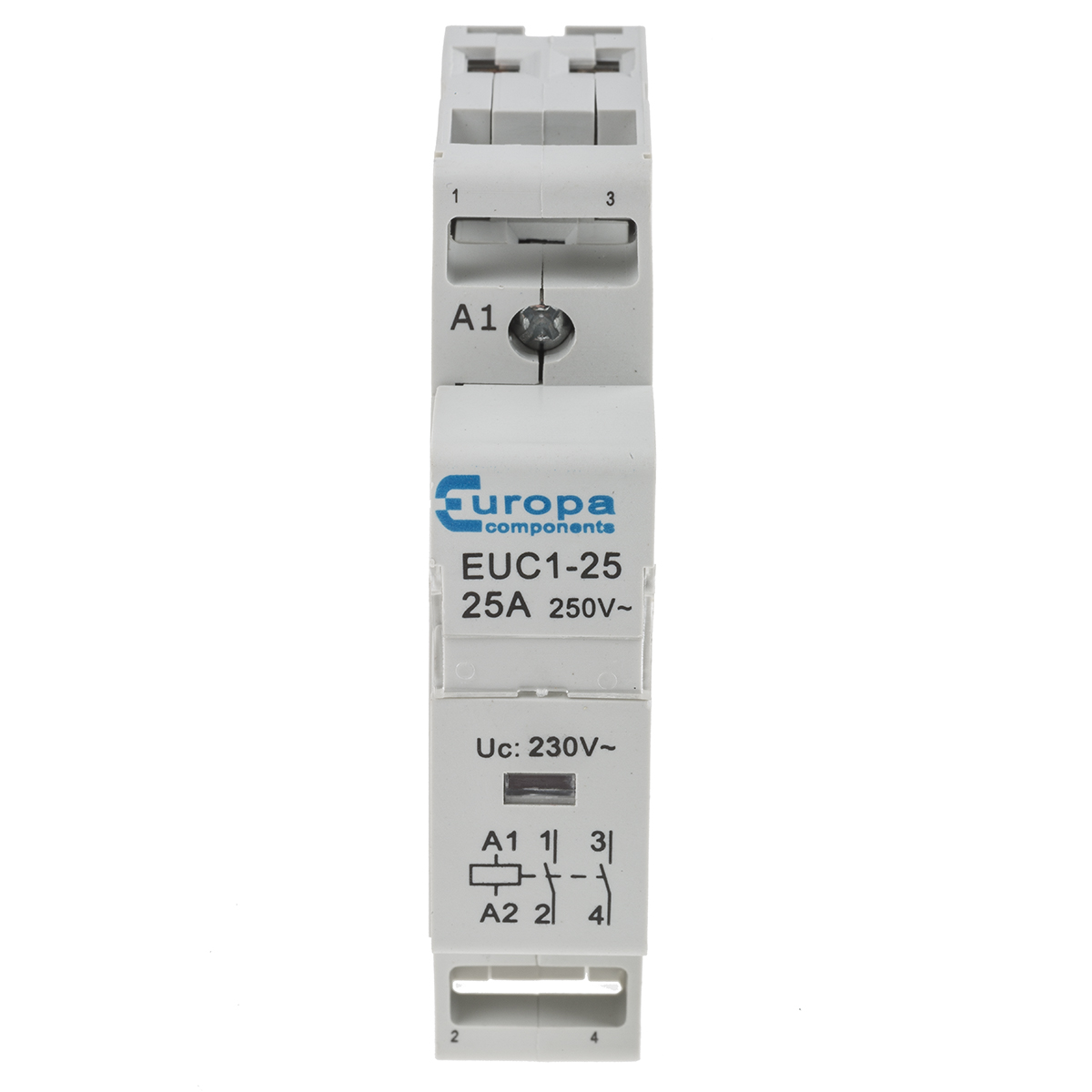
The 2N/O 25A 230V AC Contactor (Manufacturer: Europa PLC, Part ID: EUC1-25-2P) is an electrically controlled switch designed for managing high-power electrical circuits. With a 2N/O (two normally open) configuration, it is capable of handling loads up to 25A at 230V AC. This makes it ideal for industrial and commercial applications, such as motor control, HVAC systems, and lighting circuits.
Explore Projects Built with 2N/O 25A 230V AC Contactor


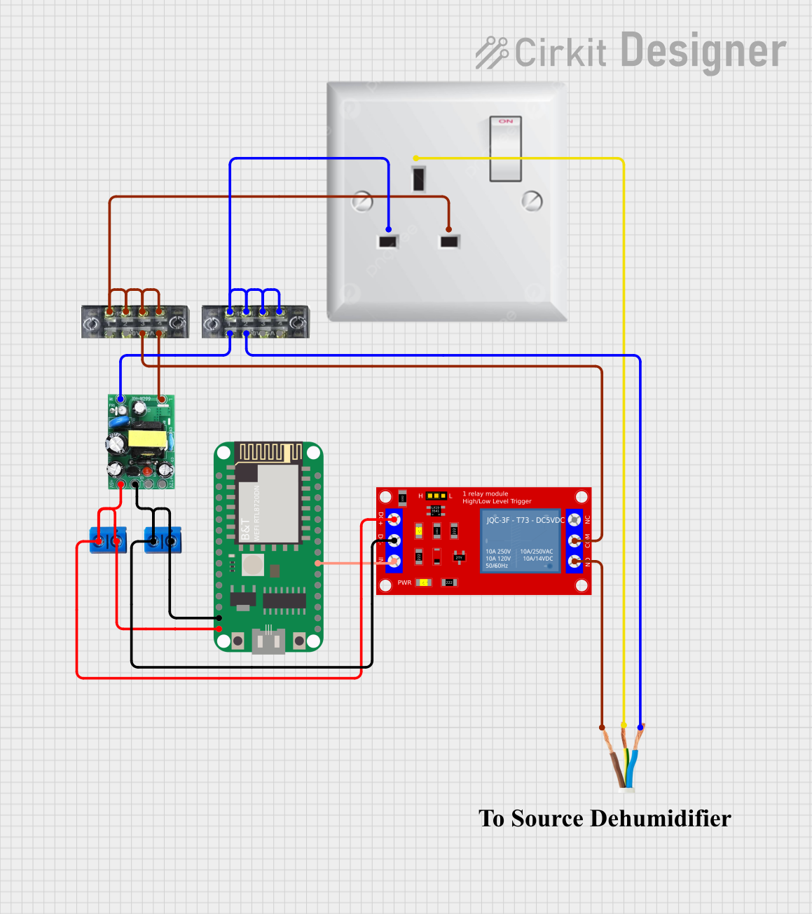
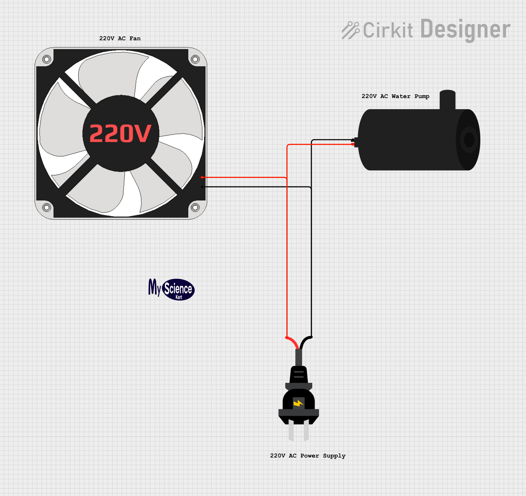
Explore Projects Built with 2N/O 25A 230V AC Contactor
Common Applications
- Motor control in industrial machinery
- Switching and controlling HVAC systems
- Lighting control in commercial buildings
- Power distribution in automation systems
Technical Specifications
Below are the key technical details and pin configuration for the EUC1-25-2P contactor:
Key Technical Details
| Parameter | Value |
|---|---|
| Manufacturer | Europa PLC |
| Part ID | EUC1-25-2P |
| Configuration | 2 Normally Open (2N/O) |
| Rated Current | 25A |
| Rated Voltage | 230V AC |
| Coil Voltage | 230V AC |
| Frequency | 50/60 Hz |
| Operating Temperature | -5°C to +40°C |
| Mechanical Durability | 1,000,000 operations |
| Electrical Durability | 100,000 operations |
| Mounting Type | DIN Rail |
| Dimensions (L x W x H) | 45mm x 58mm x 85mm |
| Weight | 0.3 kg |
Pin Configuration and Descriptions
The contactor has the following pin layout:
| Pin Number | Label | Description |
|---|---|---|
| 1 & 2 | L1, L2 | Input terminals for the main power line |
| 3 & 4 | T1, T2 | Output terminals for the load circuit |
| A1 | Coil+ | Positive terminal for the control coil |
| A2 | Coil- | Negative terminal for the control coil |
Usage Instructions
How to Use the Contactor in a Circuit
Power Supply Connection:
- Connect the main power supply (230V AC) to the input terminals L1 and L2.
- Ensure the power supply matches the rated voltage and current of the contactor.
Load Connection:
- Connect the load (e.g., motor, lighting system) to the output terminals T1 and T2.
- Verify that the load does not exceed the contactor's rated current (25A).
Control Coil Wiring:
- Connect the control circuit to the coil terminals A1 and A2.
- Apply a 230V AC signal to the coil to activate the contactor and close the normally open contacts.
Mounting:
- Secure the contactor onto a DIN rail in an enclosure to ensure safe operation.
Important Considerations and Best Practices
- Overcurrent Protection: Use a circuit breaker or fuse rated for 25A to protect the contactor and connected devices.
- Voltage Compatibility: Ensure the control coil voltage matches the specified 230V AC.
- Thermal Management: Avoid installing the contactor in environments exceeding the operating temperature range (-5°C to +40°C).
- Noise Suppression: For inductive loads, consider adding a snubber circuit or RC suppressor across the coil to reduce electrical noise.
Example: Controlling the Contactor with an Arduino UNO
The EUC1-25-2P contactor can be controlled using an Arduino UNO and a relay module. Below is an example code snippet:
// Example: Controlling a 2N/O 25A 230V AC Contactor with Arduino UNO
// This code toggles the contactor ON and OFF every 5 seconds using a relay module.

const int relayPin = 7; // Pin connected to the relay module

void setup() {
  pinMode(relayPin, OUTPUT); // Set relay pin as output
  digitalWrite(relayPin, LOW); // Ensure relay is OFF at startup
}

void loop() {
  digitalWrite(relayPin, HIGH); // Turn ON the relay (activates contactor)
  delay(5000); // Wait for 5 seconds
  digitalWrite(relayPin, LOW); // Turn OFF the relay (deactivates contactor)
  delay(5000); // Wait for 5 seconds
}
Note: Use a relay module to interface the Arduino with the contactor's control coil, as the Arduino cannot directly handle the 230V AC required by the coil.
Troubleshooting and FAQs
Common Issues and Solutions
Contactor Does Not Activate:
- Cause: No voltage applied to the control coil.
- Solution: Verify the control circuit wiring and ensure 230V AC is applied to terminals A1 and A2.
Excessive Heating:
- Cause: Overcurrent or poor ventilation.
- Solution: Check the load current and ensure it does not exceed 25A. Improve ventilation around the contactor.
Chattering Noise:
- Cause: Insufficient or unstable control voltage.
- Solution: Ensure the control voltage is stable and matches the rated 230V AC.
Contacts Stuck in Closed Position:
- Cause: Welded contacts due to overcurrent.
- Solution: Replace the contactor and ensure proper overcurrent protection is in place.
FAQs
Q1: Can this contactor be used for DC loads?
A1: No, the EUC1-25-2P is designed for AC loads only. For DC loads, use a contactor specifically rated for DC operation.
Q2: What is the maximum wire size for the terminals?
A2: The terminals can accommodate wires up to 10mm² in cross-sectional area.
Q3: Can I use this contactor for three-phase systems?
A3: No, this is a two-pole contactor designed for single-phase systems. For three-phase systems, use a three-pole contactor.
Q4: How do I test the contactor before installation?
A4: Apply 230V AC to the coil terminals A1 and A2. The contactor should click, indicating the contacts have closed.