How to Use rocker switch: Examples, Pinouts, and Specs
Introduction
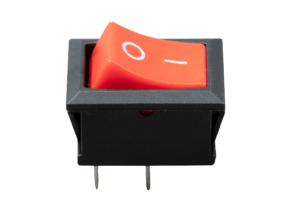
A rocker switch is a type of on/off switch that toggles between two positions, functioning as a binary device to open or close an electrical circuit. It is named for its rocking mechanism, which pivots around a central point to change the state of the switch. Rocker switches are widely used in various applications, including household appliances, automotive controls, industrial machinery, and electronic devices.
Explore Projects Built with rocker switch


Explore Projects Built with rocker switch
Common Applications and Use Cases
- Household Appliances: Light switches, power outlets, and appliance controls.
- Automotive: Dashboard switches for lights, wipers, and other accessories.
- Industrial Equipment: Control panels for machinery and equipment.
- Consumer Electronics: Power switches for computers, monitors, and peripherals.
Technical Specifications
Key Technical Details
| Specification | Detail |
|---|---|
| Voltage Rating | Typically 120-250V AC |
| Current Rating | Commonly up to 15A |
| Contact Configuration | SPST, SPDT, DPST, DPDT |
| Terminal Type | Solder, Quick Connect |
| Mounting Style | Panel Mount |
| Actuator | Rocker |
| Body Material | Plastic or Metal |
| Illumination | Optional (LED, Neon) |
Pin Configuration and Descriptions
SPST (Single Pole Single Throw)
| Pin | Description |
|---|---|
| 1 | Input (Power) |
| 2 | Output (Load) |
SPDT (Single Pole Double Throw)
| Pin | Description |
|---|---|
| 1 | Common |
| 2 | Normally Open (NO) |
| 3 | Normally Closed (NC) |
DPST (Double Pole Single Throw)
| Pin | Description |
|---|---|
| 1 | Input 1 (Power) |
| 2 | Output 1 (Load) |
| 3 | Input 2 (Power) |
| 4 | Output 2 (Load) |
DPDT (Double Pole Double Throw)
| Pin | Description |
|---|---|
| 1 | Common 1 |
| 2 | NO 1 |
| 3 | NC 1 |
| 4 | Common 2 |
| 5 | NO 2 |
| 6 | NC 2 |
Usage Instructions
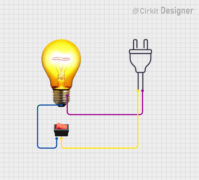
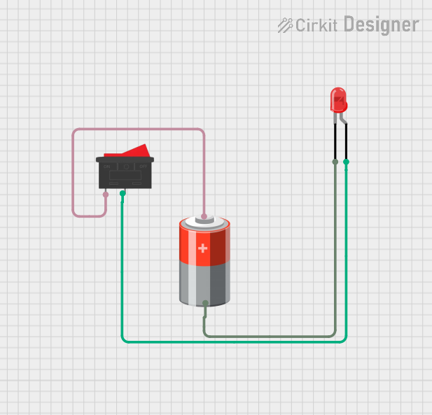
How to Use the Rocker Switch in a Circuit
- Identify the Type: Determine if the rocker switch is SPST, SPDT, DPST, or DPDT.
- Mount the Switch: Secure the switch to the panel with the mounting hardware.
- Connect the Terminals: Solder or attach quick-connect terminals to the appropriate pins.
- Test the Switch: Before applying power, ensure the switch operates smoothly and settles into each position firmly.
Important Considerations and Best Practices
- Load Rating: Do not exceed the voltage and current ratings of the switch.
- Wiring: Ensure proper insulation and strain relief for all connections.
- Environment: Use switches with appropriate ratings for moisture, dust, and temperature if used in harsh environments.
- Illumination: If using an illuminated switch, connect the additional terminals for the light source according to the manufacturer's instructions.
Troubleshooting and FAQs
Common Issues
- Switch Does Not Operate: Check for mechanical obstructions or damage to the actuator.
- Intermittent Connection: Inspect solder joints or quick-connect terminals for a secure fit.
- No Illumination (if applicable): Verify that the light source is connected correctly and has a suitable power supply.
Solutions and Tips for Troubleshooting
- Mechanical Failure: Replace the switch if it is physically damaged or worn out.
- Electrical Issues: Use a multimeter to check for continuity when the switch is in the ON position.
- Illumination Problems: Ensure that the polarity for the light source is correct, especially for LED illumination.
FAQs
Q: Can I use a rocker switch with a DC circuit? A: Yes, rocker switches can be used with both AC and DC circuits, but ensure the DC voltage and current do not exceed the switch's ratings.
Q: How do I know if my rocker switch is illuminated? A: Illuminated rocker switches typically have additional terminals for the light source and may have a clear or translucent actuator.
Q: What does SPST, SPDT, DPST, and DPDT mean? A: These acronyms refer to the internal configuration of the switch: Single Pole Single Throw, Single Pole Double Throw, Double Pole Single Throw, and Double Pole Double Throw, respectively.
Example Code for Arduino UNO
// Define the pin connected to the rocker switch
const int rockerSwitchPin = 2;

void setup() {
  // Set the rocker switch pin as input
  pinMode(rockerSwitchPin, INPUT);
  // Initialize serial communication at 9600 bits per second
  Serial.begin(9600);
}

void loop() {
  // Read the state of the rocker switch
  int switchState = digitalRead(rockerSwitchPin);

  // Print the state of the switch to the Serial Monitor
  Serial.print("Switch State: ");
  if (switchState == HIGH) {
    Serial.println("ON");
  } else {
    Serial.println("OFF");
  }

  // Delay for a bit to avoid bouncing issues
  delay(50);
}
Note: The above code assumes the rocker switch is wired to provide a HIGH signal when in the ON position. If the switch is wired to provide a LOW signal when ON, the logic in the code should be inverted accordingly.