How to Use AD8302 Amplitude Phase RF Detector (2.7GHz ): Examples, Pinouts, and Specs
Introduction
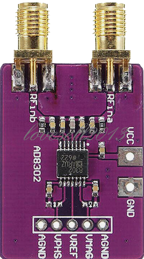
The AD8302 is a fully integrated system for measuring gain/loss and phase in numerous applications including RF/IF instrumentation and communications. Its capability to measure amplitude and phase between two independent signals makes it ideal for applications such as RF/IF PA linearization, antenna alignment, and phase detection. The AD8302 operates over a specified frequency range of 2.7 GHz with a measurement range of 60 dB and phase measurement range of 0 to 180 degrees.
Explore Projects Built with AD8302 Amplitude Phase RF Detector (2.7GHz )

Explore Projects Built with AD8302 Amplitude Phase RF Detector (2.7GHz )
Common Applications
- RF/IF PA linearization
- Antenna alignment
- Phase detection and measurement
- Vector modulation analysis
- Network analysis
Technical Specifications
Key Technical Details
- Frequency Range: 2.7 GHz
- Measurement Range: 60 dB
- Phase Measurement Range: 0 to 180 degrees
- Supply Voltage: 2.7 V to 5.5 V
- Operating Temperature: -40°C to +85°C
Pin Configuration and Descriptions
| Pin Number | Name | Description |
|---|---|---|
| 1 | VPOS | Positive supply voltage (2.7 V to 5.5 V) |
| 2 | INPA | Input signal A |
| 3 | INPB | Input signal B |
| 4 | FILT | Filter capacitor connection |
| 5 | VOUT | Voltage output proportional to phase difference |
| 6 | VMAG | Voltage output proportional to magnitude difference |
| 7 | GND | Ground connection |
| 8 | REFOUT | Reference voltage output (1.8 V typical) |
| 9 | DETLO | Detector low voltage |
| 10 | DETLO | Detector high voltage |
Usage Instructions
How to Use the Component in a Circuit
Power Supply: Connect the VPOS pin to a clean power supply between 2.7 V and 5.5 V. Ensure that the GND pin is connected to the system ground.
Input Signals: Apply the two RF signals to be compared to INPA and INPB. These inputs are high impedance and should be driven with a source impedance of 50 ohms for accurate measurements.
Output Filtering: Connect a capacitor from the FILT pin to ground to set the low-pass filter cutoff frequency for the VOUT and VMAG outputs.
Outputs: VMAG provides an output voltage proportional to the logarithm of the amplitude ratio of INPA to INPB, while VOUT provides an output voltage proportional to the phase difference between the two inputs.
Reference Voltage: REFOUT provides a stable reference voltage of 1.8 V which can be used for setting thresholds or as a reference for ADCs.
Important Considerations and Best Practices
- Ensure that the input signals are within the specified frequency range and power levels to avoid damaging the device.
- Use bypass capacitors close to the VPOS and GND pins to minimize noise and supply ripple.
- Keep the signal paths as short as possible to reduce the effects of parasitic inductances and capacitances.
- Avoid running input signal traces parallel to each other to minimize crosstalk.
- The FILT capacitor should be chosen based on the desired response time and noise filtering requirements.
Troubleshooting and FAQs
Common Issues
- Inaccurate Measurements: Ensure that the input signals are properly matched and within the specified range. Check for proper power supply decoupling and filtering.
- No Output: Verify that the power supply is within the specified range and that all pins are correctly connected.
- Unstable Outputs: Check the FILT capacitor and ensure that it is correctly sized for your application.
Solutions and Tips
- Use a spectrum analyzer to verify the frequency and power level of the input signals.
- Ensure that the PCB layout minimizes noise coupling and signal path lengths.
- If experiencing instability, increase the value of the FILT capacitor to improve filtering.
FAQs
Q: Can the AD8302 be used for signals outside the 2.7 GHz range? A: The AD8302 is optimized for up to 2.7 GHz. Performance may degrade outside this range.
Q: What is the power consumption of the AD8302? A: The typical supply current is 30 mA at 5 V, which equates to a power consumption of 150 mW.
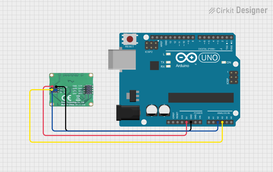
Q: How can I interface the AD8302 with a microcontroller or an Arduino? A: The VMAG and VOUT outputs can be connected to the analog inputs of a microcontroller or an Arduino. Use the REFOUT as a reference voltage if needed.
Example Code for Arduino UNO
// Define the analog pins connected to the AD8302 outputs
const int phasePin = A0; // VOUT connected to A0
const int magnitudePin = A1; // VMAG connected to A1

void setup() {
  // Initialize serial communication
  Serial.begin(9600);
}

void loop() {
  // Read the voltage outputs from the AD8302
  int phaseValue = analogRead(phasePin);
  int magnitudeValue = analogRead(magnitudePin);

  // Convert the readings to voltage (assuming a 5V Arduino)
  float phaseVoltage = (phaseValue * 5.0) / 1023.0;
  float magnitudeVoltage = (magnitudeValue * 5.0) / 1023.0;

  // Print the results to the serial monitor
  Serial.print("Phase Voltage: ");
  Serial.print(phaseVoltage);
  Serial.print(" V, Magnitude Voltage: ");
  Serial.print(magnitudeVoltage);
  Serial.println(" V");

  // Wait for a short period before reading again
  delay(500);
}
This example code reads the phase and magnitude voltages from the AD8302 and prints them to the serial monitor. Ensure that the analog reference voltage is set to the same voltage as the VPOS supply if it is different from 5V.