How to Use SPX29302: Examples, Pinouts, and Specs
Introduction
The SPX29302 is a low-dropout (LDO) voltage regulator integrated circuit (IC) designed to provide a stable and reliable voltage supply. It is particularly useful in power management circuits and portable electronic devices where maintaining a consistent voltage level is critical. The SPX29302 is known for its low dropout voltage, meaning it can regulate output voltage effectively even when the input voltage is very close to the output voltage, making it an efficient choice for battery-powered applications.
Explore Projects Built with SPX29302


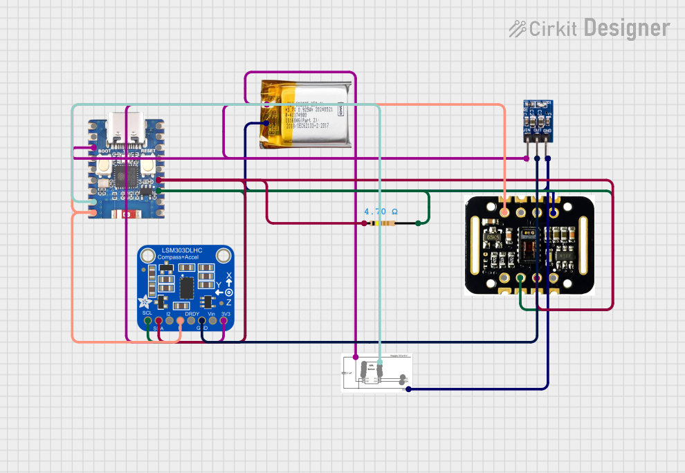

Explore Projects Built with SPX29302
Common Applications
- Power supplies for microcontrollers and digital systems
- Battery-powered devices
- Portable electronics
- Linear power regulators for embedded systems
Technical Specifications
Key Technical Details
- Output Voltage Range: Adjustable or fixed (1.5V, 1.8V, 2.5V, 3.3V, 5V)
- Dropout Voltage: Typically 330mV at 3A
- Output Current: Up to 3A
- Input Voltage Range: Up to 16V
- Quiescent Current: 5mA (typical)
- Package: TO-263, TO-220, and others
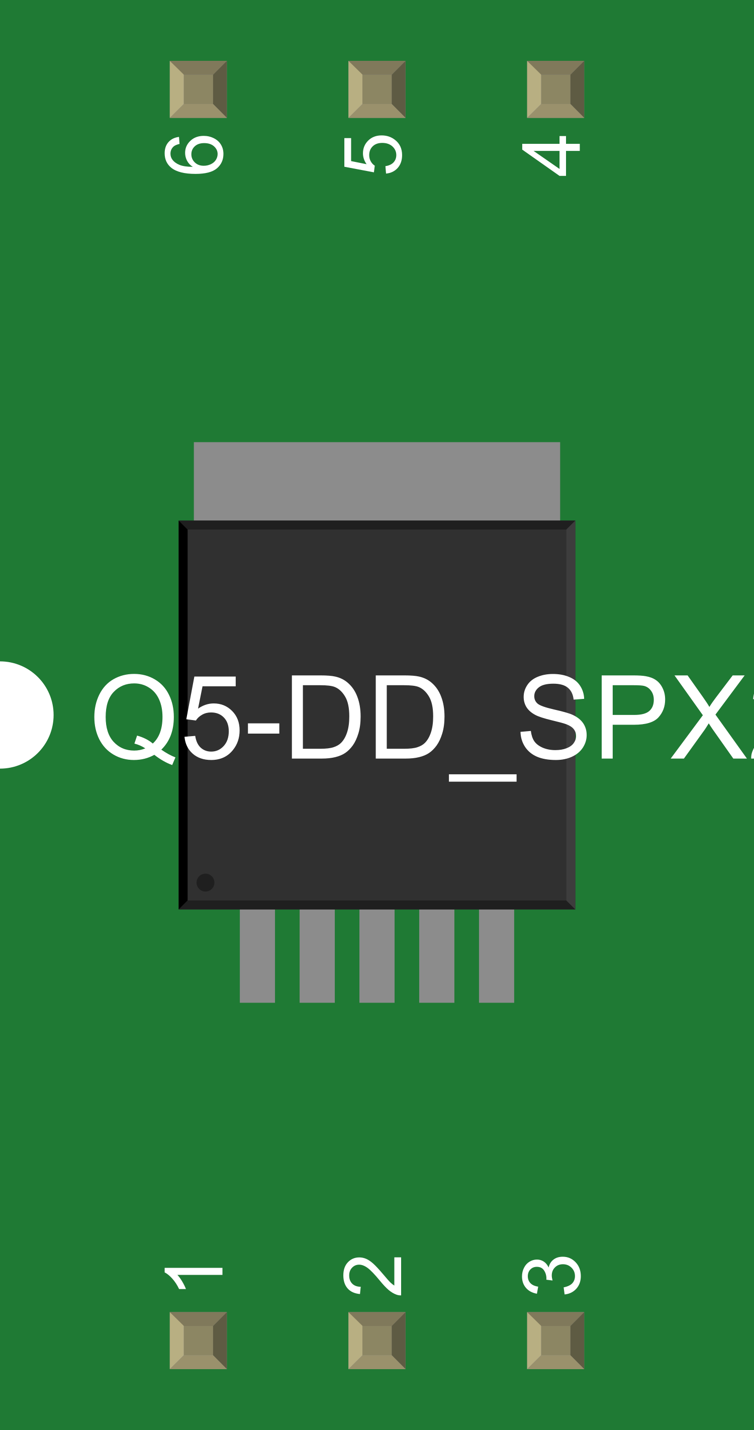
Pin Configuration and Descriptions
| Pin Number | Name | Description |
|---|---|---|
| 1 | ADJ/GND | Ground pin (for fixed output versions) or adjustment pin (for adjustable output versions) |
| 2 | OUT | Regulated output voltage |
| 3 | IN | Input voltage |
Usage Instructions
How to Use the SPX29302 in a Circuit
- Input Voltage: Ensure that the input voltage (Vin) is within the specified range and at least 1.5V higher than the desired output voltage for optimal performance.
- Output Voltage: For adjustable versions, connect a resistor divider from the output to the ADJ pin to set the output voltage. For fixed versions, the ADJ pin is grounded.
- Capacitors: Place a capacitor (typically 10µF or greater) close to the IN pin and another capacitor close to the OUT pin to stabilize the voltage and reduce noise.
- Heat Dissipation: Consider the power dissipation and ensure adequate heat sinking if the regulator is expected to handle high currents.
Important Considerations and Best Practices
- Always consult the datasheet for the specific version of the SPX29302 you are using.
- Ensure that the input voltage does not exceed the maximum rating to prevent damage.
- Use capacitors with low equivalent series resistance (ESR) for better performance.
- Avoid running the regulator at its maximum current rating for extended periods to prevent overheating.
Troubleshooting and FAQs
Common Issues
- Output Voltage Fluctuation: Ensure that the input voltage is stable and that the capacitors are of adequate value and quality.
- Overheating: Check for proper heat sinking and verify that the current draw is within the specified limits.
Solutions and Tips
- If the output voltage is incorrect, check the resistor divider values (for adjustable versions) and ensure they are within tolerance.
- For thermal issues, improve airflow, add a heat sink, or reduce the load current.
FAQs
Q: Can the SPX29302 be used with an Arduino UNO? A: Yes, it can be used to provide a stable voltage supply to an Arduino UNO or any other compatible microcontroller.
Q: What is the maximum input voltage for the SPX29302? A: The maximum input voltage is 16V. Always verify with the datasheet for the specific version you are using.
Q: How do I adjust the output voltage on the adjustable version? A: Use a resistor divider connected between the OUT pin, the ADJ pin, and ground. The output voltage is set according to the formula specified in the datasheet.
Example Code for Arduino UNO
// Example code to demonstrate how to power an Arduino UNO using the SPX29302

void setup() {
  // Initialize digital pin LED_BUILTIN as an output.
  pinMode(LED_BUILTIN, OUTPUT);
}

void loop() {
  // Turn the LED on (HIGH is the voltage level)
  digitalWrite(LED_BUILTIN, HIGH);
  // Wait for a second
  delay(1000);
  // Turn the LED off by making the voltage LOW
  digitalWrite(LED_BUILTIN, LOW);
   // Wait for a second
  delay(1000);
}

// Note: This code assumes that the SPX29302 is configured to provide
// the correct voltage to the Arduino UNO (5V for most boards).
// The SPX29302 itself does not require any specific code to operate.
Remember, this code is for demonstration purposes and assumes that the SPX29302 is already configured and supplying power to the Arduino UNO. Always ensure that the voltage levels are appropriate for your specific microcontroller or electronic component.