How to Use Rev V3 Color Sensor: Examples, Pinouts, and Specs
Introduction
The Rev V3 Color Sensor (Manufacturer Part ID: APDS-9151) is a compact and versatile sensor designed to detect and identify colors by analyzing the light reflected from objects. Manufactured by Rev Robotics, this sensor is widely used in robotics, automation, and other applications requiring precise color recognition. Its ability to measure red, green, blue, and clear light intensity makes it an essential component for tasks such as object sorting, line following, and environmental sensing.
Explore Projects Built with Rev V3 Color Sensor
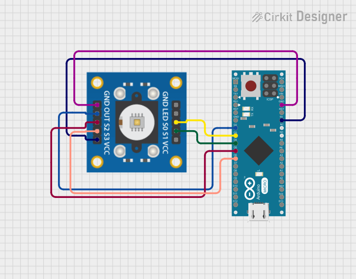
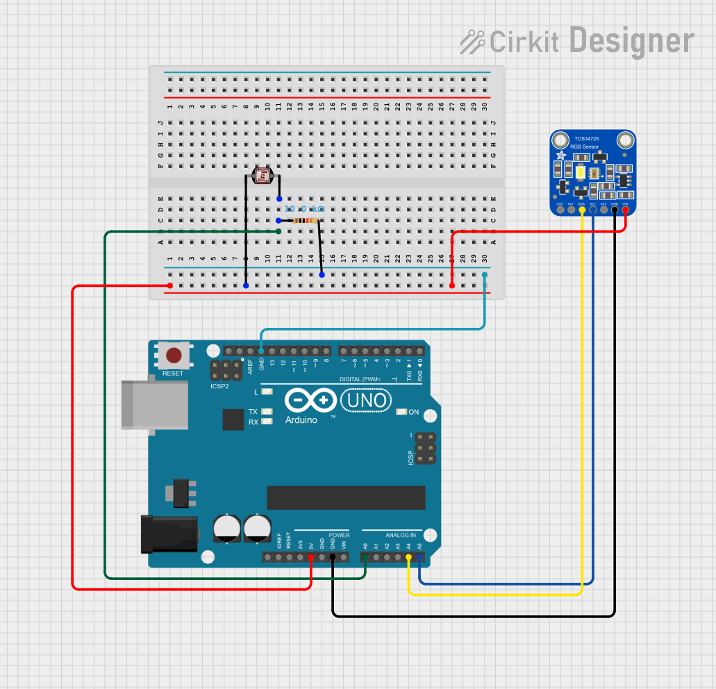

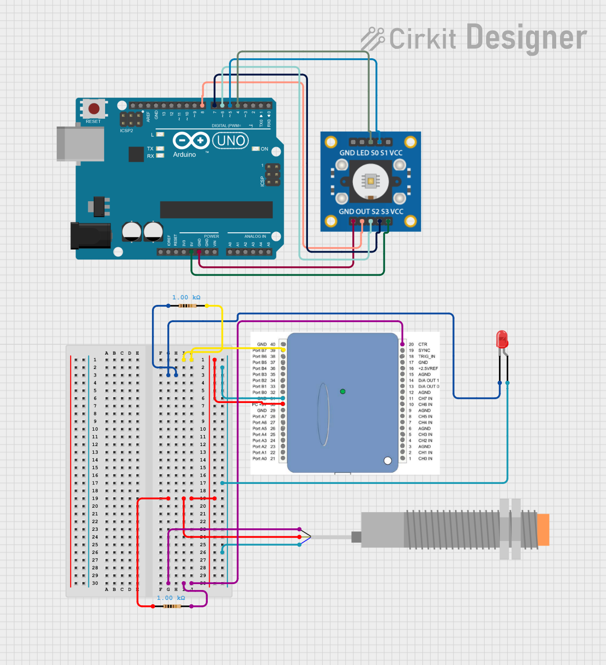
Explore Projects Built with Rev V3 Color Sensor
Common Applications and Use Cases
- Robotics: Line-following robots, object sorting by color, and environmental sensing.
- Automation: Quality control in manufacturing processes and color-based sorting systems.
- Education: STEM projects and learning platforms for color detection and analysis.
- Consumer Electronics: Color-based user interfaces and lighting control systems.
Technical Specifications
The following table outlines the key technical details of the Rev V3 Color Sensor:
| Parameter | Value |
|---|---|
| Manufacturer | Rev Robotics |
| Part ID | APDS-9151 |
| Supply Voltage | 3.0V to 3.6V |
| Operating Current | 0.2 mA (typical) |
| Communication Protocol | I2C |
| I2C Address | 0x39 (default) |
| Measurement Range | Red, Green, Blue, and Clear light intensity |
| Integration Time | Configurable (2.78 ms to 712 ms) |
| Operating Temperature | -40°C to +85°C |
| Dimensions | 20mm x 20mm x 5mm |
Pin Configuration and Descriptions
The Rev V3 Color Sensor has a 4-pin interface for easy integration into circuits. The pinout is as follows:
| Pin | Name | Description |
|---|---|---|
| 1 | VCC | Power supply input (3.0V to 3.6V) |
| 2 | GND | Ground |
| 3 | SDA | I2C data line |
| 4 | SCL | I2C clock line |
Usage Instructions
How to Use the Component in a Circuit
- Power the Sensor: Connect the VCC pin to a 3.3V power source and the GND pin to ground.
- I2C Communication: Connect the SDA and SCL pins to the corresponding I2C pins on your microcontroller (e.g., Arduino UNO).
- Pull-Up Resistors: Ensure that the I2C lines (SDA and SCL) have pull-up resistors (typically 4.7kΩ) if not already present on your microcontroller.
- Initialization: Use the I2C address (0x39 by default) to communicate with the sensor and configure its settings (e.g., integration time).
Important Considerations and Best Practices
- Ambient Light: Minimize ambient light interference by shielding the sensor or using it in controlled lighting conditions.
- Distance to Object: Maintain a consistent distance between the sensor and the object for accurate color readings.
- Calibration: Calibrate the sensor for your specific application to improve accuracy.
- Power Supply: Use a stable 3.3V power source to avoid fluctuations in readings.
Example Code for Arduino UNO
Below is an example Arduino sketch to interface with the Rev V3 Color Sensor:
#include <Wire.h>

// I2C address of the Rev V3 Color Sensor
#define COLOR_SENSOR_ADDR 0x39

void setup() {
  Wire.begin(); // Initialize I2C communication
  Serial.begin(9600); // Initialize serial communication for debugging

  // Configure the sensor (e.g., enable RGBC and set integration time)
  Wire.beginTransmission(COLOR_SENSOR_ADDR);
  Wire.write(0x80); // Command register to enable RGBC
  Wire.write(0x03); // Enable RGBC and power on
  Wire.endTransmission();

  Serial.println("Rev V3 Color Sensor Initialized");
}

void loop() {
  // Request color data from the sensor
  Wire.beginTransmission(COLOR_SENSOR_ADDR);
  Wire.write(0x94); // Address of the data register for clear light
  Wire.endTransmission();
  Wire.requestFrom(COLOR_SENSOR_ADDR, 8); // Request 8 bytes of data

  if (Wire.available() == 8) {
    uint16_t clear = Wire.read() | (Wire.read() << 8);
    uint16_t red = Wire.read() | (Wire.read() << 8);
    uint16_t green = Wire.read() | (Wire.read() << 8);
    uint16_t blue = Wire.read() | (Wire.read() << 8);

    // Print the color data to the serial monitor
    Serial.print("Clear: "); Serial.print(clear);
    Serial.print(" Red: "); Serial.print(red);
    Serial.print(" Green: "); Serial.print(green);
    Serial.print(" Blue: "); Serial.println(blue);
  }

  delay(500); // Wait for 500ms before the next reading
}
Troubleshooting and FAQs
Common Issues and Solutions
No Data from Sensor:
- Ensure the sensor is powered correctly (3.3V on VCC and GND connected).
- Verify the I2C connections (SDA and SCL) and check for loose wires.
- Confirm the I2C address (default is 0x39) matches the one in your code.
Inaccurate Color Readings:
- Calibrate the sensor for your specific application.
- Reduce ambient light interference by shielding the sensor.
- Maintain a consistent distance between the sensor and the object.
I2C Communication Errors:
- Check for proper pull-up resistors on the SDA and SCL lines.
- Ensure the microcontroller supports 3.3V logic levels or use a level shifter.
FAQs
Q: Can the sensor detect colors in complete darkness?
A: No, the sensor requires some light to reflect off the object. You can use an external light source for consistent readings.Q: What is the maximum distance for accurate color detection?
A: The optimal distance is typically 1-2 cm, but this may vary depending on the object's reflectivity and ambient light conditions.Q: Can I use this sensor with a 5V microcontroller?
A: Yes, but you will need a level shifter to safely interface the 3.3V sensor with a 5V microcontroller.
This documentation provides a comprehensive guide to using the Rev V3 Color Sensor (APDS-9151) effectively in your projects. For further assistance, refer to the manufacturer's datasheet or support resources.