How to Use 12v 4 Pin Common Vehicle Relay: Examples, Pinouts, and Specs
Introduction
The 12V 4 Pin Common Vehicle Relay is an electromechanical switch designed to control high-current devices using a low-current signal. It operates at 12 volts, making it ideal for automotive applications. This relay is widely used in vehicles to control components such as headlights, horns, fuel pumps, and cooling fans. Its compact design and four-pin configuration make it easy to integrate into various circuits.
Explore Projects Built with 12v 4 Pin Common Vehicle Relay


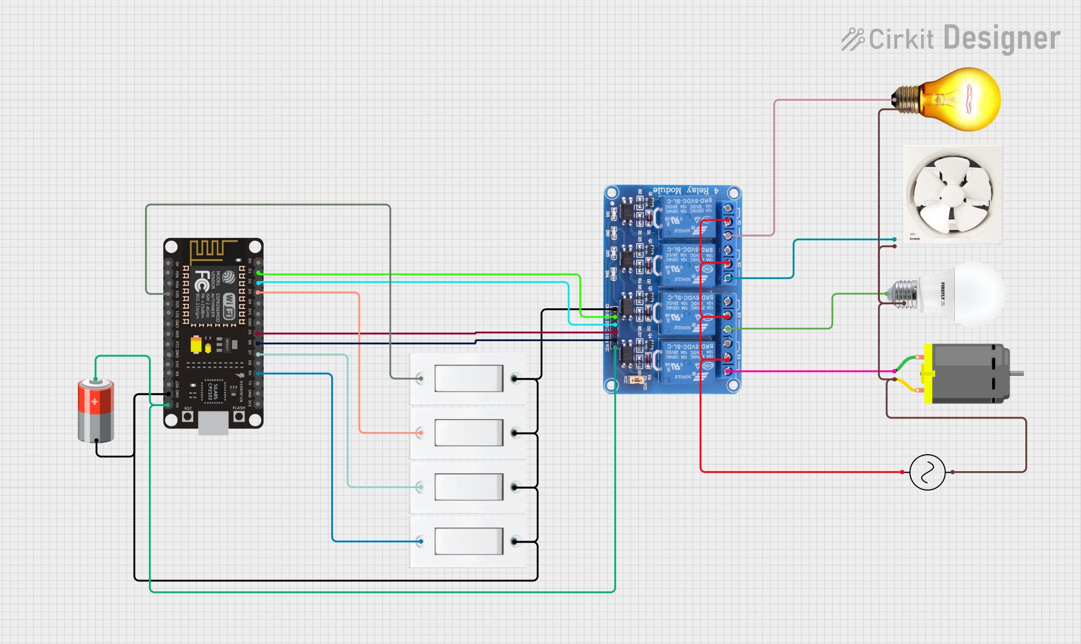
Explore Projects Built with 12v 4 Pin Common Vehicle Relay
Common Applications and Use Cases
- Automotive lighting systems (e.g., headlights, fog lights)
- Horn and alarm systems
- Fuel pump control
- Radiator cooling fan control
- Power window and door lock systems
- General-purpose switching in automotive and industrial circuits
Technical Specifications
The following table outlines the key technical details of the 12V 4 Pin Common Vehicle Relay:
| Parameter | Value |
|---|---|
| Operating Voltage | 12V DC |
| Coil Resistance | ~85 Ohms |
| Contact Rating | 30A at 12V DC |
| Contact Configuration | SPST (Single Pole Single Throw) |
| Pin Count | 4 |
| Dimensions | ~28mm x 28mm x 25mm |
| Operating Temperature | -40°C to +85°C |
| Insulation Resistance | ≥100MΩ at 500V DC |
| Dielectric Strength | 500V AC for 1 minute |
Pin Configuration and Descriptions
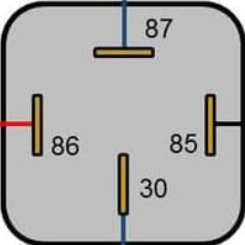
The 12V 4 Pin Common Vehicle Relay has the following pin configuration:
| Pin Number | Name | Description |
|---|---|---|
| 85 | Coil (-) | Connects to the negative terminal of the control signal (ground). |
| 86 | Coil (+) | Connects to the positive terminal of the control signal (12V DC). |
| 30 | Common (COM) | The input terminal for the high-current load. |
| 87 | Normally Open (NO) | The output terminal that connects to the load when the relay is activated. |
Usage Instructions
How to Use the Component in a Circuit
- Identify the Pins: Refer to the pin configuration table to correctly identify the pins (85, 86, 30, and 87).
- Connect the Coil:
- Pin 85 should be connected to the ground (negative terminal of the control circuit).
- Pin 86 should be connected to the positive terminal of the control signal (12V DC).
- Connect the Load:
- Pin 30 should be connected to the positive terminal of the power source for the load.
- Pin 87 should be connected to one terminal of the load. The other terminal of the load should be connected to the ground.
- Activate the Relay: When a 12V DC signal is applied across pins 85 and 86, the relay will activate, allowing current to flow from pin 30 to pin 87 and powering the connected load.
Important Considerations and Best Practices
- Diode Protection: To prevent voltage spikes caused by the relay coil, connect a flyback diode (e.g., 1N4007) across pins 85 and 86. The cathode (marked end) should face pin 86.
- Current Rating: Ensure the load current does not exceed the relay's contact rating of 30A.
- Secure Connections: Use appropriate connectors or soldering to ensure reliable connections, especially in automotive environments where vibrations are common.
- Power Source: Use a stable 12V DC power source to avoid relay malfunction.
Example: Connecting to an Arduino UNO
The 12V 4 Pin Common Vehicle Relay can be controlled using an Arduino UNO. Below is an example circuit and code to toggle a relay using a digital output pin.
Circuit Connections
- Connect pin 85 of the relay to the Arduino GND.
- Connect pin 86 of the relay to an Arduino digital pin (e.g., D7) through a 1kΩ resistor.
- Connect pin 30 to the positive terminal of a 12V power source.
- Connect pin 87 to one terminal of the load (e.g., a 12V LED or motor). The other terminal of the load should be connected to the ground.
Arduino Code
// Define the relay control pin
const int relayPin = 7;

void setup() {
  // Set the relay pin as an output
  pinMode(relayPin, OUTPUT);

  // Ensure the relay is off initially
  digitalWrite(relayPin, LOW);
}

void loop() {
  // Turn the relay on
  digitalWrite(relayPin, HIGH);
  delay(1000); // Keep the relay on for 1 second

  // Turn the relay off
  digitalWrite(relayPin, LOW);
  delay(1000); // Keep the relay off for 1 second
}
Troubleshooting and FAQs
Common Issues and Solutions
Relay Not Activating:
- Cause: Insufficient voltage or current to the coil.
- Solution: Ensure the control signal provides 12V DC and sufficient current (typically ~140mA).
Load Not Powering On:
- Cause: Incorrect wiring of pins 30 and 87.
- Solution: Double-check the connections to ensure pin 30 is connected to the power source and pin 87 to the load.
Relay Buzzing Noise:
- Cause: Unstable or insufficient control signal voltage.
- Solution: Use a stable 12V DC power source and check for loose connections.
Voltage Spikes Damaging Components:
- Cause: Lack of flyback diode across the coil.
- Solution: Install a flyback diode (e.g., 1N4007) across pins 85 and 86.
FAQs
Q: Can this relay handle AC loads?
A: No, this relay is designed for DC loads only. Using it with AC loads may damage the relay.Q: What happens if I reverse the coil connections (pins 85 and 86)?
A: The relay will not activate. Ensure correct polarity when connecting the coil.Q: Can I use this relay for a load exceeding 30A?
A: No, exceeding the rated current may cause overheating and damage the relay contacts.Q: Is the relay waterproof?
A: Most 12V 4 Pin Vehicle Relays are not waterproof. Use a waterproof relay or enclosure for outdoor applications.