How to Use H11AA1M: Examples, Pinouts, and Specs
Introduction
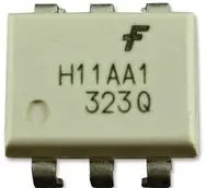
The H11AA1M is an optocoupler designed to provide electrical isolation between its input and output. It consists of an internal light-emitting diode (LED) and a phototransistor, which work together to transmit signals optically while maintaining complete electrical separation. This isolation is crucial in applications where different voltage levels need to interface or where sensitive components must be protected from high voltages or electrical noise.
Explore Projects Built with H11AA1M
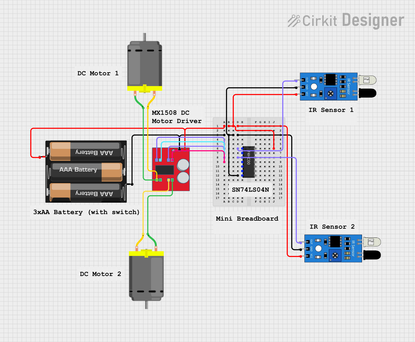

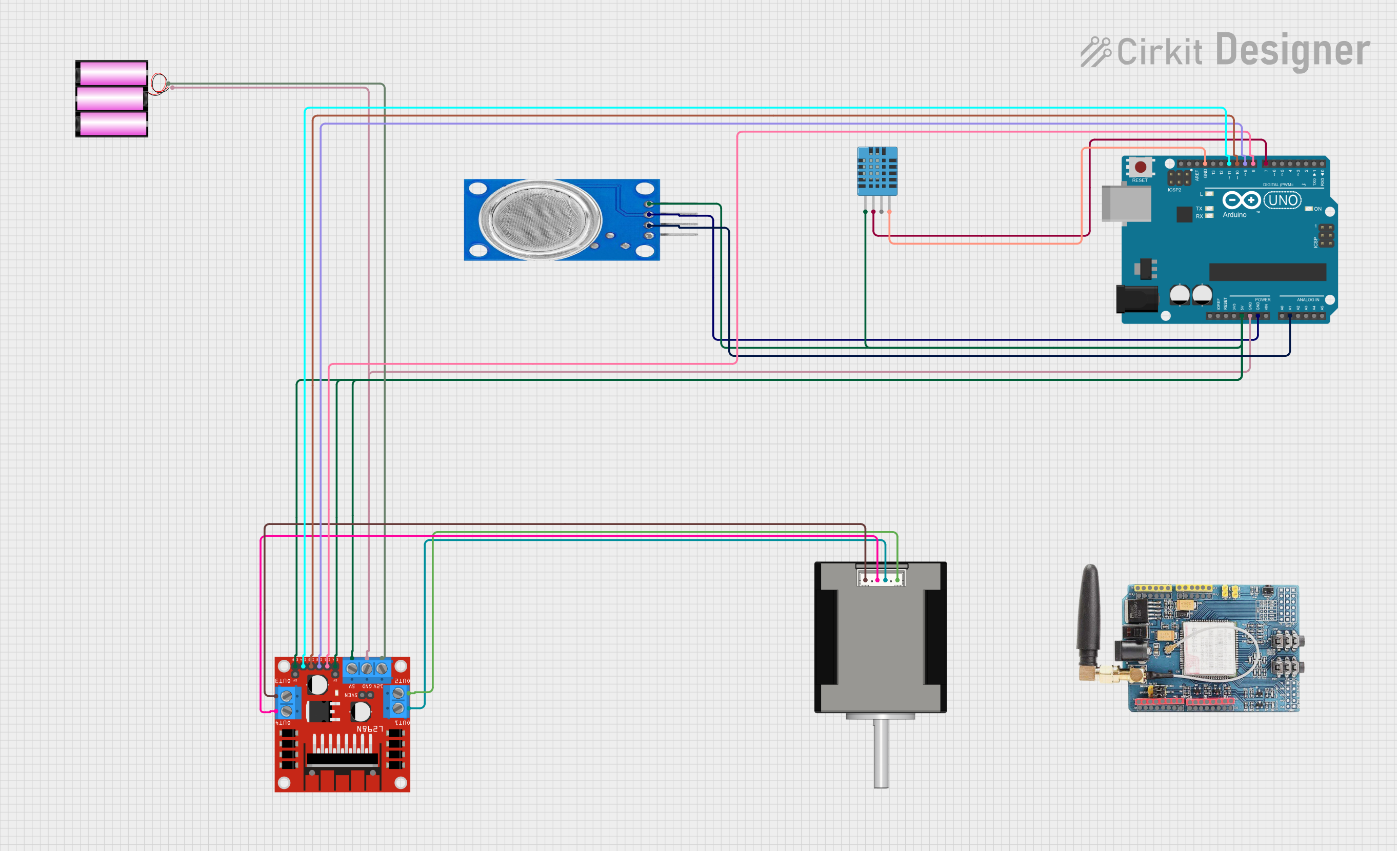
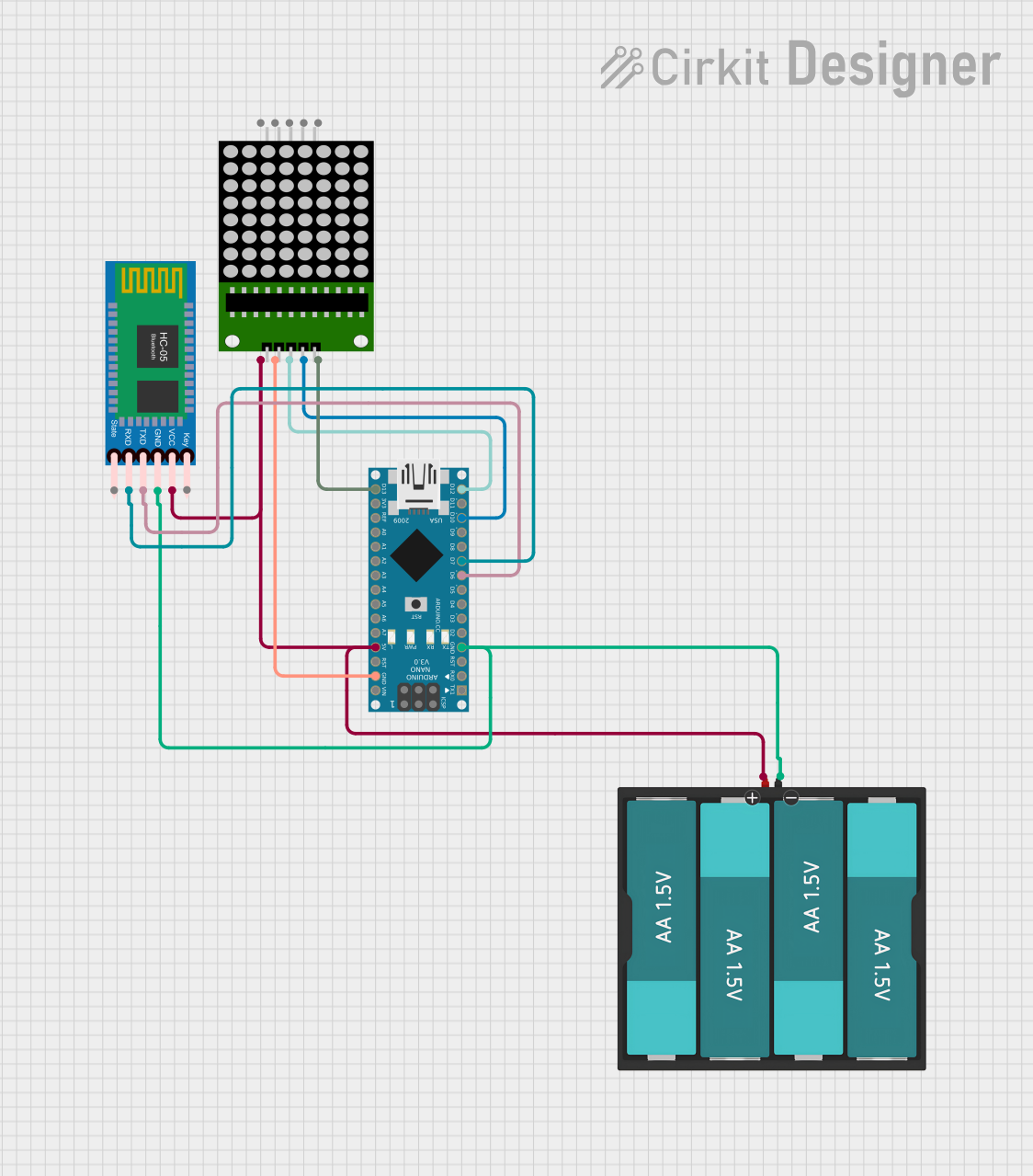
Explore Projects Built with H11AA1M
Common Applications and Use Cases
- Signal isolation in microcontroller circuits
- Interfacing between high-voltage and low-voltage systems
- Protecting sensitive components from voltage spikes or surges
- AC line monitoring and zero-crossing detection
- Industrial control systems and motor drives
Technical Specifications
Key Technical Details
| Parameter | Value |
|---|---|
| Input LED Forward Voltage | 1.2V (typical), 1.5V (maximum) |
| Input LED Forward Current | 10mA (typical), 60mA (maximum) |
| Output Collector-Emitter Voltage | 30V (maximum) |
| Isolation Voltage | 5300 VRMS |
| Current Transfer Ratio (CTR) | 20% to 50% |
| Operating Temperature Range | -55°C to +100°C |
| Package Type | 6-pin DIP |
Pin Configuration and Descriptions
| Pin Number | Name | Description |
|---|---|---|
| 1 | Anode (LED) | Positive terminal of the internal LED. |
| 2 | Cathode (LED) | Negative terminal of the internal LED. |
| 3 | NC (No Connection) | Not connected internally. Leave unconnected. |
| 4 | Emitter (Transistor) | Emitter terminal of the phototransistor. |
| 5 | Collector (Transistor) | Collector terminal of the phototransistor. |
| 6 | NC (No Connection) | Not connected internally. Leave unconnected. |
Usage Instructions
How to Use the H11AA1M in a Circuit
Input Side (LED):
- Connect a current-limiting resistor in series with the LED (pins 1 and 2) to prevent excessive current. The resistor value can be calculated using Ohm's law:
[ R = \frac{V_{in} - V_f}{I_f} ]
Where (V_{in}) is the input voltage, (V_f) is the forward voltage of the LED (1.2V typical), and (I_f) is the desired forward current (e.g., 10mA).
- Connect a current-limiting resistor in series with the LED (pins 1 and 2) to prevent excessive current. The resistor value can be calculated using Ohm's law:
Output Side (Phototransistor):
- Connect the collector (pin 5) to the positive supply voltage through a pull-up resistor. The emitter (pin 4) is connected to ground.
- The value of the pull-up resistor depends on the desired output signal characteristics and the supply voltage.
Isolation:
- Ensure that the input and output sides are electrically isolated. Do not connect the grounds of the input and output circuits.
Important Considerations and Best Practices
- Current Limiting: Always use a resistor to limit the current through the LED to avoid damage.
- Voltage Ratings: Do not exceed the maximum voltage ratings for the collector-emitter voltage or the isolation voltage.
- Temperature Range: Ensure the operating environment is within the specified temperature range (-55°C to +100°C).
- Signal Speed: The H11AA1M is suitable for low-speed signal transmission. For high-speed applications, consider optocouplers designed for faster switching.
Example: Connecting the H11AA1M to an Arduino UNO
The following example demonstrates how to use the H11AA1M to detect an AC signal and interface it with an Arduino UNO.
Circuit Setup
- Connect the LED side (pins 1 and 2) to an AC signal source through a current-limiting resistor.
- On the output side, connect the collector (pin 5) to the Arduino's digital input pin through a pull-up resistor, and connect the emitter (pin 4) to ground.
Arduino Code
// Define the digital pin connected to the H11AA1M output
const int optoInputPin = 2;

void setup() {
  pinMode(optoInputPin, INPUT); // Set the pin as input
  Serial.begin(9600);          // Initialize serial communication
}

void loop() {
  int signalState = digitalRead(optoInputPin); // Read the optocoupler output

  // Print the signal state to the Serial Monitor
  if (signalState == HIGH) {
    Serial.println("AC signal detected: HIGH");
  } else {
    Serial.println("AC signal detected: LOW");
  }

  delay(500); // Add a delay for readability
}
Troubleshooting and FAQs
Common Issues and Solutions
No Output Signal:
- Cause: The LED current is too low.
- Solution: Check the current-limiting resistor value and ensure the input current is within the specified range (10mA typical).
Output Signal is Unstable:
- Cause: Noise or insufficient pull-up resistor value.
- Solution: Use a lower-value pull-up resistor to strengthen the signal or add a capacitor for noise filtering.
Component Overheating:
- Cause: Excessive current through the LED or phototransistor.
- Solution: Verify that the current-limiting resistor and pull-up resistor values are appropriate.
No Isolation Achieved:
- Cause: Input and output grounds are connected.
- Solution: Ensure complete electrical isolation between the input and output sides.
FAQs
Q: Can the H11AA1M be used for high-speed data transmission?
A: No, the H11AA1M is designed for low-speed signal isolation. For high-speed applications, consider optocouplers with faster response times.
Q: What is the maximum AC voltage the H11AA1M can handle?
A: The H11AA1M does not directly handle AC voltage. Use a current-limiting resistor to ensure the LED current stays within the specified range.
Q: Can I use the H11AA1M for DC signal isolation?
A: Yes, the H11AA1M can isolate DC signals as well as low-frequency AC signals.
Q: How do I calculate the pull-up resistor value?
A: The pull-up resistor value depends on the supply voltage and desired output current. A typical value is 10kΩ for 5V systems.