
How to Use BALUN: Examples, Pinouts, and Specs
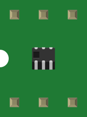
 Design with BALUN in Cirkit Designer
Introduction
A balun (short for "balanced to unbalanced") is a type of electrical transformer designed to convert signals between balanced and unbalanced formats. Balanced signals have equal and opposite voltages on two conductors, while unbalanced signals have a single conductor with a reference to ground. Baluns are widely used in radio frequency (RF) applications, antenna systems, and audio equipment to improve signal integrity, reduce interference, and ensure proper impedance matching.
Explore Projects Built with BALUN
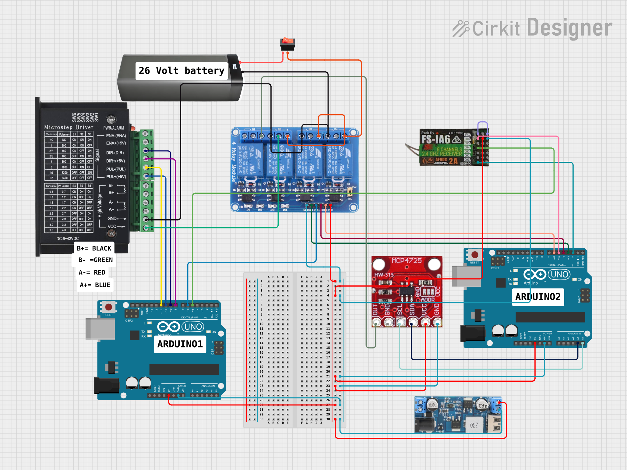 Open Project in Cirkit Designer
 Open Project in Cirkit Designer
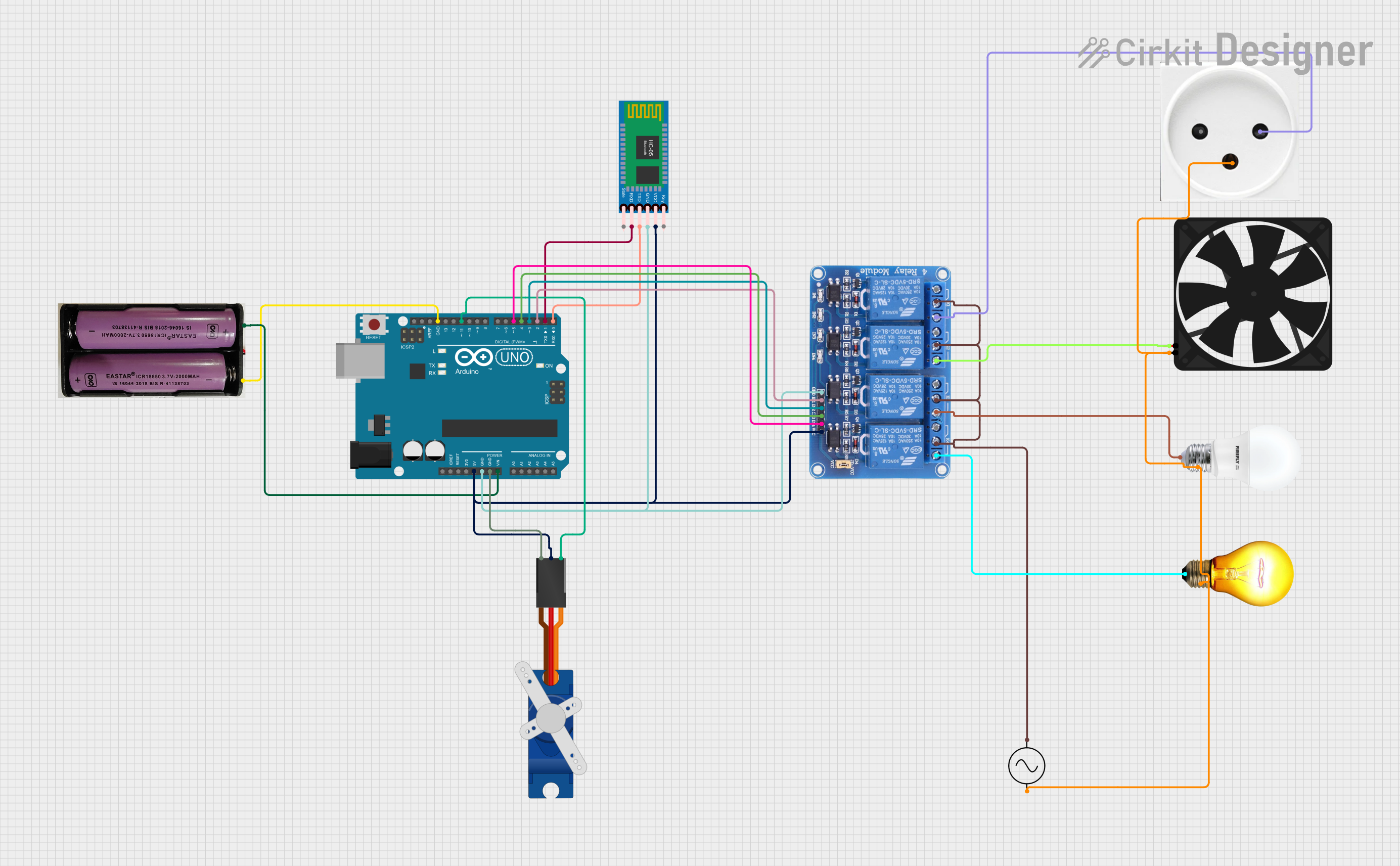 Open Project in Cirkit Designer
 Open Project in Cirkit Designer
Explore Projects Built with BALUN
Open Project in Cirkit DesignerOpen Project in Cirkit DesignerOpen Project in Cirkit DesignerOpen Project in Cirkit DesignerCommon Applications and Use Cases
- RF transmission and reception systems
- Antenna matching for ham radios, TV antennas, and Wi-Fi systems
- Audio signal conversion in professional audio equipment
- Impedance matching in transmission lines
- Noise reduction in communication systems
Technical Specifications
The technical specifications of a balun can vary depending on its type and application. Below are general specifications for a typical RF balun:
| Parameter | Specification |
|---|---|
| Frequency Range | 1 MHz to 3 GHz (varies by model) |
| Impedance Ratio | 1:1, 4:1, or custom (application-specific) |
| Power Handling | Up to 100 W (depends on design) |
| Insertion Loss | < 1 dB |
| Return Loss | > 20 dB |
| Operating Temperature | -40°C to +85°C |
Pin Configuration and Descriptions
Baluns typically have three or more terminals. Below is a general pin configuration for a 1:1 RF balun:
| Pin | Description |
|---|---|
| Pin 1 | Balanced input/output (positive signal) |
| Pin 2 | Balanced input/output (negative signal) |
| Pin 3 | Unbalanced input/output (signal and ground reference) |
For other types of baluns, such as 4:1 impedance ratio baluns, additional pins may be present for specific configurations.
Usage Instructions
How to Use the Balun in a Circuit
- Determine the Application: Identify whether the balun is needed for impedance matching, signal conversion, or noise reduction.
- Connect the Balanced Side: Attach the balanced signal source (e.g., a differential signal from an antenna) to the balanced terminals (Pin 1 and Pin 2).
- Connect the Unbalanced Side: Attach the unbalanced signal source (e.g., a coaxial cable) to the unbalanced terminal (Pin 3).
- Impedance Matching: Ensure the balun's impedance ratio matches the impedance of the connected devices to minimize signal loss.
- Grounding: Properly ground the unbalanced side to reduce noise and interference.
Important Considerations and Best Practices
- Frequency Range: Verify that the balun supports the operating frequency of your application.
- Power Handling: Ensure the balun can handle the power level of your system to avoid damage.
- Orientation: Install the balun in the correct orientation to maintain signal integrity.
- Shielding: Use shielded cables and proper grounding to minimize electromagnetic interference (EMI).
- Testing: Use a network analyzer to verify the balun's performance, including insertion loss and return loss.
Example: Using a Balun with an Arduino UNO
While baluns are not directly connected to microcontrollers like the Arduino UNO, they can be used in RF communication modules or antenna systems interfaced with the Arduino. Below is an example of using a balun in an RF antenna system for a 433 MHz transmitter module:
// Example: Arduino code for transmitting data using a 433 MHz RF module
// Ensure the RF module is connected to an antenna via a balun for signal integrity.

#include <VirtualWire.h> // Include the VirtualWire library for RF communication

void setup() {
  vw_setup(2000); // Set the data rate to 2000 bits per second
  vw_set_tx_pin(12); // Set the transmit pin to digital pin 12
}

void loop() {
  const char *msg = "Hello, World!"; // Message to transmit
  vw_send((uint8_t *)msg, strlen(msg)); // Send the message
  vw_wait_tx(); // Wait for the transmission to complete
  delay(1000); // Wait 1 second before sending the next message
}
Note: Ensure the balun is correctly installed between the RF module and the antenna to improve signal quality and reduce interference.
Troubleshooting and FAQs
Common Issues and Solutions
Signal Loss or Weak Signal
- Cause: Incorrect impedance matching or poor connections.
- Solution: Verify the impedance ratio of the balun and ensure proper connections.
High Noise or Interference
- Cause: Improper grounding or lack of shielding.
- Solution: Ground the unbalanced side properly and use shielded cables.
Overheating
- Cause: Exceeding the balun's power handling capacity.
- Solution: Use a balun rated for higher power or reduce the power level.
Frequency Mismatch
- Cause: Operating the balun outside its specified frequency range.
- Solution: Select a balun designed for the desired frequency range.
FAQs
Q: Can I use a balun for audio applications?
A: Yes, baluns are commonly used in professional audio systems to convert between balanced and unbalanced audio signals, reducing noise and interference.
Q: How do I choose the right balun for my application?
A: Consider the frequency range, impedance ratio, power handling, and application type (e.g., RF, audio) when selecting a balun.
Q: Can a balun be used for both transmission and reception?
A: Yes, baluns are bidirectional and can be used for both transmitting and receiving signals.
Q: Do I need a balun for my antenna system?
A: If your antenna system involves converting between balanced and unbalanced signals or requires impedance matching, a balun is recommended.