How to Use Adafruit ANO Rotary Encoder to I2C Adapter: Examples, Pinouts, and Specs
Introduction
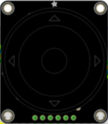
The Adafruit ANO Rotary Encoder to I2C Adapter is a compact module designed to simplify the integration of a rotary encoder into projects that utilize the I2C communication protocol. Rotary encoders are electromechanical devices that convert the angular position or motion of a shaft or axle to an analog or digital signal. This adapter allows for the rotary encoder's output to be easily read over the I2C bus, making it ideal for applications such as user interfaces, menu navigation, or input devices in embedded systems.
Explore Projects Built with Adafruit ANO Rotary Encoder to I2C Adapter
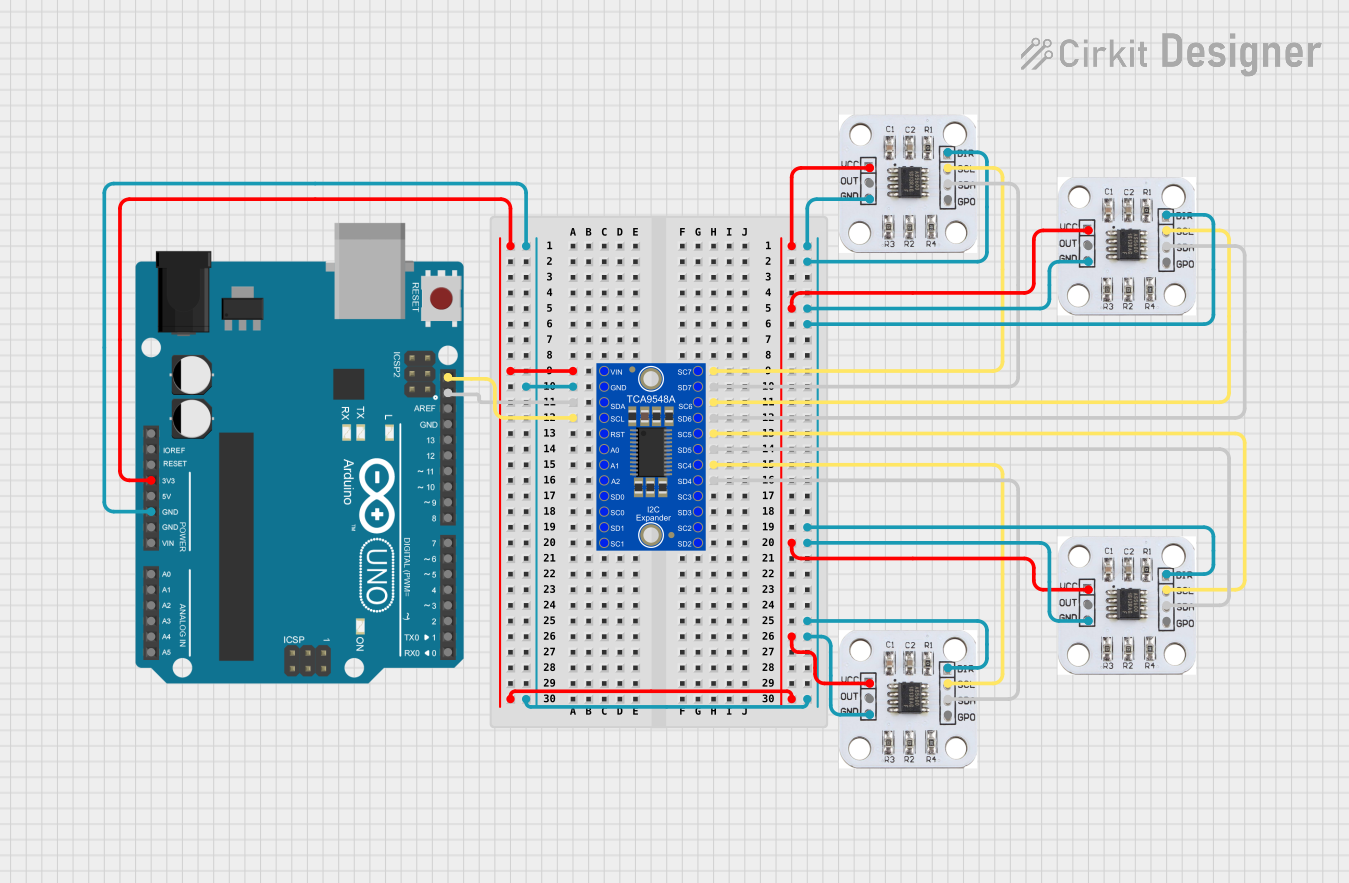
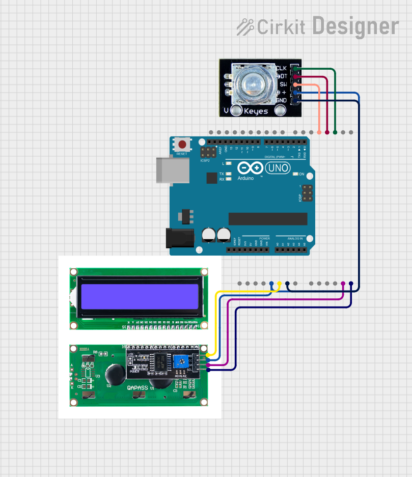
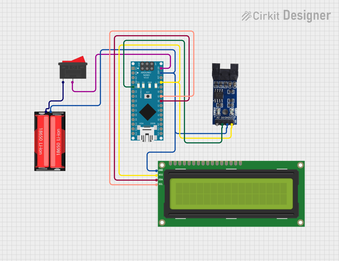

Explore Projects Built with Adafruit ANO Rotary Encoder to I2C Adapter
Common Applications and Use Cases
- Volume control in audio equipment
- Menu selection in user interfaces
- Position input for robotics
- Scrolling input for displays
Technical Specifications
Key Technical Details
- Operating Voltage: 3.3V to 5V
- I2C Address: Configurable
- Dimensions: 18mm x 18mm x 2mm
Pin Configuration and Descriptions
| Pin | Description |
|---|---|
| GND | Ground |
| VCC | Power supply (3.3V to 5V) |
| SDA | I2C Data Line |
| SCL | I2C Clock Line |
| INT | Interrupt (optional use) |
Usage Instructions
Connecting the Adapter to a Circuit
- Connect the
VCCpin to the power supply (3.3V or 5V, depending on your system). - Connect the
GNDpin to the ground of your system. - Connect the
SDAandSCLpins to the I2C data and clock lines, respectively. - (Optional) Connect the
INTpin to an interrupt-capable pin on your microcontroller if you wish to use the interrupt feature.
Important Considerations and Best Practices
- Ensure that pull-up resistors are in place for the
SDAandSCLlines if they are not already provided by the microcontroller. - Avoid long wires for the I2C connection to minimize signal degradation.
- Use the interrupt pin to detect rotary encoder changes without polling the I2C bus, which can save power and processing time.
Example Code for Arduino UNO
#include <Wire.h>

// Define the I2C address for the rotary encoder (check your module documentation)
#define ENCODER_I2C_ADDRESS 0x40

void setup() {
  Wire.begin(); // Join the I2C bus as a master
  Serial.begin(9600); // Start serial communication for debugging
}

void loop() {
  Wire.requestFrom(ENCODER_I2C_ADDRESS, 2); // Request 2 bytes from the encoder
  if(Wire.available() == 2) {
    int position = Wire.read(); // Read the first byte, which is the low byte
    position |= Wire.read() << 8; // Read the second byte, which is the high byte
    Serial.println(position); // Print the position value to the serial monitor
  }
  delay(100); // Small delay to prevent spamming the I2C bus
}
Troubleshooting and FAQs
Common Issues
- I2C Communication Failure: Ensure that the
SDAandSCLlines are connected correctly and that pull-up resistors are in place. - Inaccurate Position Values: Check for any mechanical issues with the rotary encoder or electrical noise affecting the signal.
Solutions and Tips for Troubleshooting
- Use the Arduino's built-in
Wirelibrary functions such asWire.beginTransmission()andWire.endTransmission()to check for errors in communication. - If using the interrupt feature, ensure that the microcontroller's interrupt pin is configured correctly in your code.
FAQs
Q: Can I change the I2C address of the adapter? A: Yes, the I2C address is configurable. Refer to the Adafruit documentation for the specific procedure.
Q: What is the maximum rotation speed the adapter can handle? A: The maximum rotation speed will depend on the specific rotary encoder used and the I2C bus speed. Check the datasheet of your rotary encoder for more details.
Q: Is it possible to connect multiple encoders to the same I2C bus? A: Yes, as long as each encoder has a unique I2C address, you can connect multiple encoders to the same bus.
Remember to consult the Adafruit ANO Rotary Encoder to I2C Adapter datasheet for more detailed information and specifications.