
How to Use sim800c development board: Examples, Pinouts, and Specs
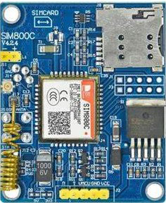
 Design with sim800c development board in Cirkit Designer
Introduction
The SIM800C Development Board is a compact GSM/GPRS module designed for mobile communication. It enables devices to send and receive SMS, make voice calls, and connect to the internet via cellular networks. This versatile module is widely used in IoT applications, remote monitoring systems, and embedded projects requiring cellular connectivity. Its small size, low power consumption, and rich set of features make it an ideal choice for developers and hobbyists alike.
Explore Projects Built with sim800c development board
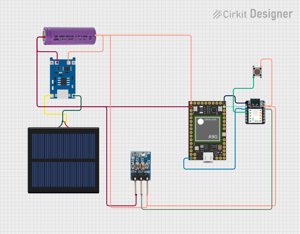 Open Project in Cirkit Designer
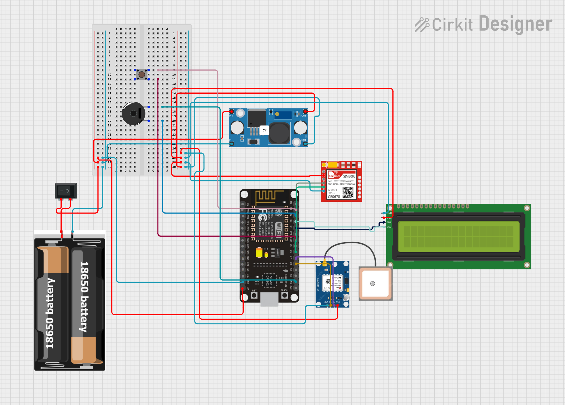 Open Project in Cirkit Designer
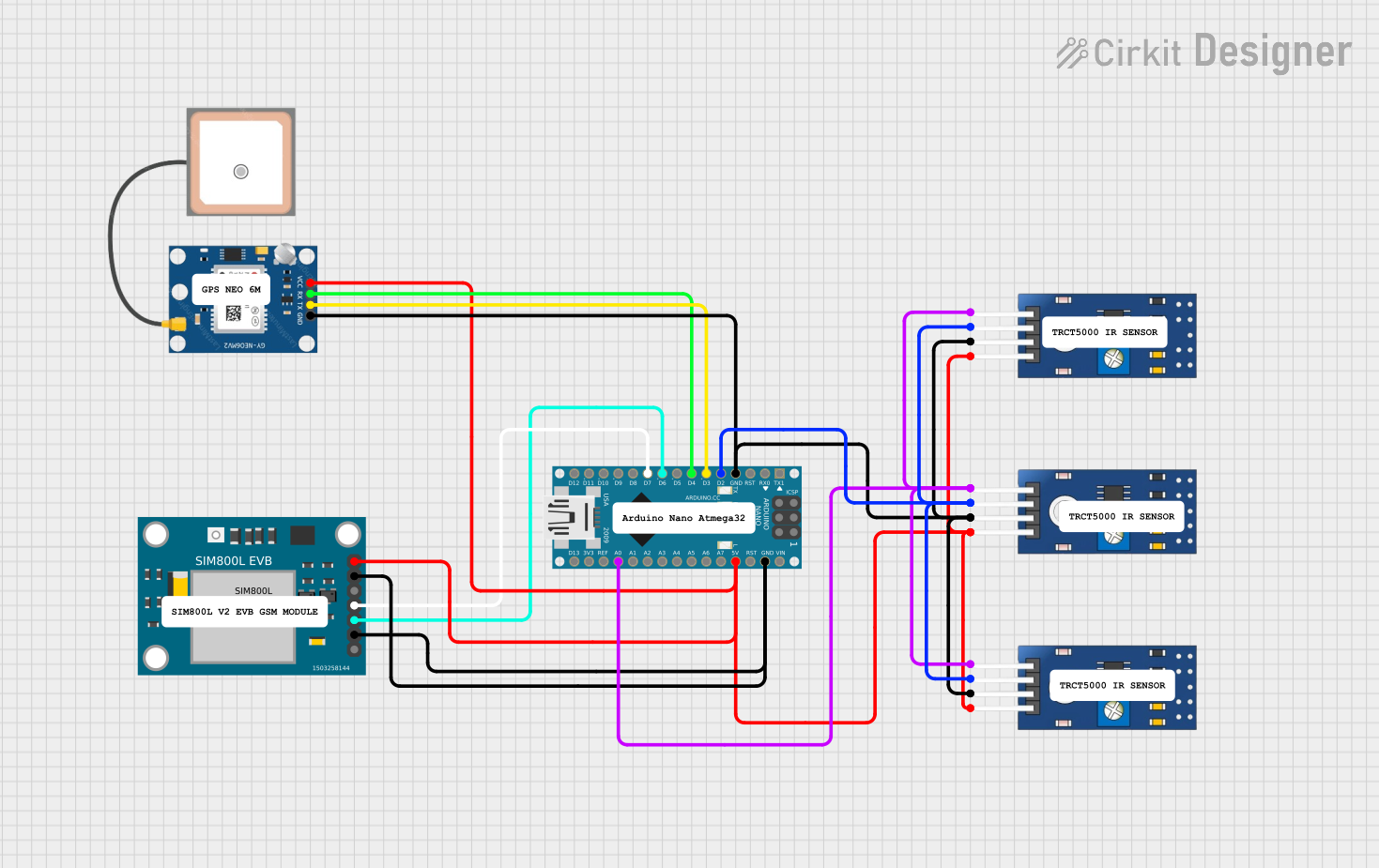 Open Project in Cirkit Designer
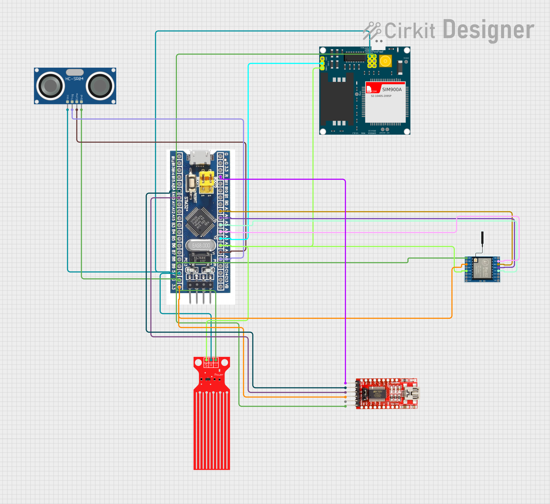 Open Project in Cirkit Designer
Explore Projects Built with sim800c development board
Open Project in Cirkit DesignerOpen Project in Cirkit DesignerOpen Project in Cirkit DesignerOpen Project in Cirkit DesignerCommon Applications and Use Cases
- IoT devices for remote data transmission
- Home automation systems
- GPS tracking and fleet management
- SMS-based alert systems
- Voice call-enabled embedded systems
- Internet connectivity for microcontrollers
Technical Specifications
The SIM800C Development Board is built around the SIM800C GSM/GPRS module, offering robust performance and a wide range of features. Below are the key technical details:
Key Technical Details
| Parameter | Specification |
|---|---|
| Operating Voltage | 3.4V to 4.4V |
| Operating Current | Idle: ~20mA, Max: ~2A (during TX burst) |
| Frequency Bands | GSM 850/900/1800/1900 MHz |
| GPRS Connectivity | Class 12 |
| SMS Support | Text and PDU modes |
| Voice Call Support | Full-duplex |
| UART Baud Rate | 1200 to 115200 bps |
| Dimensions | ~24mm x 24mm x 3mm (module only) |
| Operating Temperature | -40°C to +85°C |
Pin Configuration and Descriptions
The SIM800C Development Board typically includes a breakout for the module's pins. Below is a table describing the key pins:
| Pin Name | Description |
|---|---|
| VCC | Power input (3.4V to 4.4V). Ensure a stable power supply for proper operation. |
| GND | Ground connection. |
| TXD | UART Transmit pin. Connect to the RX pin of the microcontroller. |
| RXD | UART Receive pin. Connect to the TX pin of the microcontroller. |
| DTR | Data Terminal Ready. Used for sleep mode control. |
| RST | Reset pin. Active low. Pull low to reset the module. |
| NETLIGHT | Network status indicator. Blinks to indicate GSM network status. |
| MIC+ / MIC- | Microphone input pins for voice calls. |
| SPK+ / SPK- | Speaker output pins for voice calls. |
Usage Instructions
How to Use the SIM800C Development Board in a Circuit
- Power Supply: Provide a stable power supply of 3.7V to 4.2V. A Li-ion battery or a DC-DC converter is recommended. Ensure the power source can supply up to 2A during transmission bursts.
- UART Communication: Connect the TXD and RXD pins of the SIM800C to the RX and TX pins of your microcontroller, respectively. Use a logic level converter if your microcontroller operates at 5V logic.
- Antenna Connection: Attach a GSM antenna to the antenna connector for proper signal reception.
- SIM Card: Insert a valid SIM card into the SIM card slot.
- Initialization: Use AT commands to configure and control the module. For example, send
ATto check communication andAT+CSQto check signal quality.
Important Considerations and Best Practices
- Power Supply: Ensure the power supply is capable of handling high current spikes (up to 2A). Use capacitors (e.g., 1000µF) near the module to stabilize the voltage.
- Antenna Placement: Place the antenna away from other components to avoid interference.
- UART Baud Rate: Configure the UART baud rate to match the module's default (usually 9600 bps) or set it using the
AT+IPRcommand. - Sleep Mode: Use the DTR pin to enable sleep mode for power saving in battery-powered applications.
Example: Connecting to an Arduino UNO
Below is an example of how to use the SIM800C Development Board with an Arduino UNO to send an SMS:
Circuit Connections
| SIM800C Pin | Arduino UNO Pin |
|---|---|
| VCC | 5V (via a step-down regulator to 4V) |
| GND | GND |
| TXD | D2 (via a voltage divider for 5V to 3.3V conversion) |
| RXD | D3 |
Arduino Code
#include <SoftwareSerial.h>

// Define RX and TX pins for SoftwareSerial
SoftwareSerial sim800c(2, 3); // RX = D2, TX = D3

void setup() {
  // Initialize serial communication
  Serial.begin(9600); // For debugging
  sim800c.begin(9600); // SIM800C baud rate

  Serial.println("Initializing SIM800C...");
  delay(1000);

  // Test communication with the module
  sim800c.println("AT"); // Send AT command
  delay(1000);
  while (sim800c.available()) {
    Serial.write(sim800c.read()); // Print response to Serial Monitor
  }

  // Send an SMS
  sim800c.println("AT+CMGF=1"); // Set SMS mode to text
  delay(1000);
  sim800c.println("AT+CMGS=\"+1234567890\""); // Replace with recipient's number
  delay(1000);
  sim800c.print("Hello from SIM800C!"); // SMS content
  delay(1000);
  sim800c.write(26); // Send Ctrl+Z to send the SMS
  Serial.println("SMS sent!");
}

void loop() {
  // Nothing to do here
}
Troubleshooting and FAQs
Common Issues and Solutions
Module Not Responding to AT Commands
- Cause: Incorrect UART connections or baud rate mismatch.
- Solution: Verify TXD and RXD connections. Ensure the baud rate matches the module's default (9600 bps).
No Network Connection
- Cause: Poor signal strength or incorrect SIM card placement.
- Solution: Check the antenna connection and ensure the SIM card is properly inserted. Use the
AT+CSQcommand to check signal strength.
Module Restarts During Operation
- Cause: Insufficient power supply.
- Solution: Use a power source capable of supplying at least 2A. Add capacitors near the module to stabilize the voltage.
SMS Not Sent
- Cause: Incorrect SMS mode or recipient number.
- Solution: Ensure SMS mode is set to text (
AT+CMGF=1) and the recipient number is in international format.
FAQs
Q1: Can the SIM800C connect to 3G or 4G networks?
A1: No, the SIM800C only supports GSM/GPRS (2G) networks.
Q2: How can I reduce power consumption?
A2: Use the DTR pin to enable sleep mode and reduce power consumption during idle periods.
Q3: What is the maximum length of an SMS?
A3: The maximum length is 160 characters for a single SMS in text mode. Longer messages are split into multiple SMS.
Q4: Can I use the SIM800C for GPS tracking?
A4: The SIM800C does not have built-in GPS functionality. However, it can be used alongside a GPS module to transmit location data.
This concludes the documentation for the SIM800C Development Board.