How to Use Emergency Stop Push Button: Examples, Pinouts, and Specs
Introduction
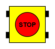
The Emergency Stop Push Button (Manufacturer: EAO, Part ID: 61-3440.4/1) is a critical safety device designed to immediately halt machinery or equipment during emergencies. It ensures quick access and response to prevent accidents, protecting both personnel and equipment. This push button is commonly used in industrial machinery, automation systems, and other environments where safety is paramount.
Explore Projects Built with Emergency Stop Push Button

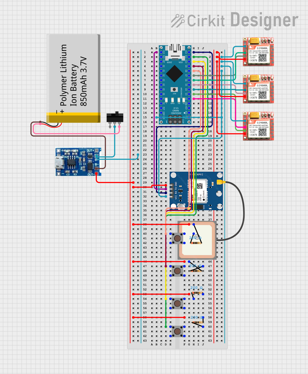
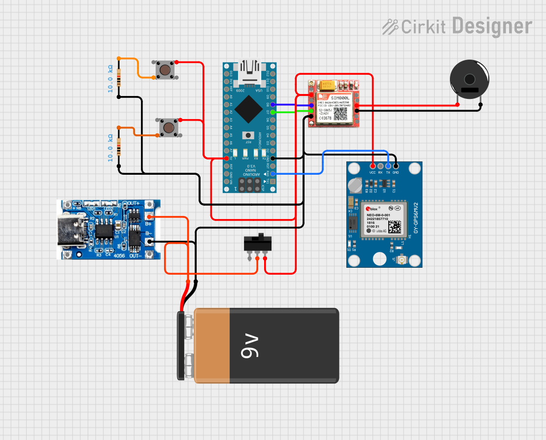
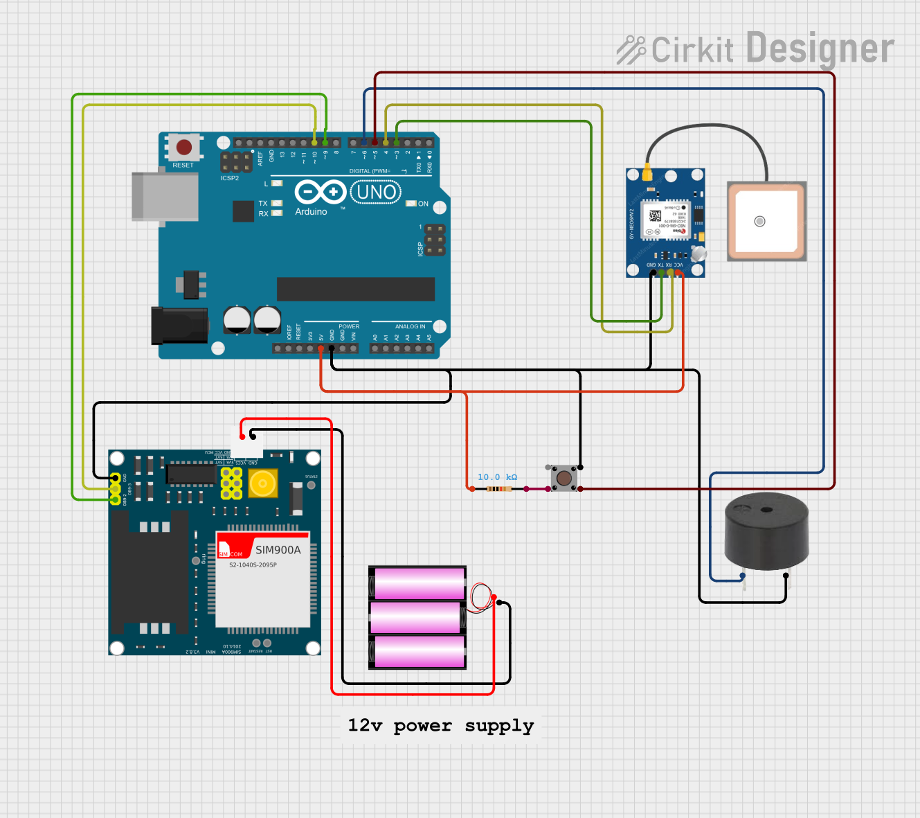
Explore Projects Built with Emergency Stop Push Button
Common Applications and Use Cases
- Industrial machinery and manufacturing lines
- Automation systems and robotic equipment
- Elevators and escalators
- Conveyor systems
- Laboratory and testing equipment
- Any system requiring immediate shutdown in emergencies
Technical Specifications
The following table outlines the key technical details of the EAO Emergency Stop Push Button (61-3440.4/1):
| Parameter | Specification |
|---|---|
| Manufacturer | EAO |
| Part ID | 61-3440.4/1 |
| Operating Voltage | 24V DC / 230V AC |
| Current Rating | 10A |
| Contact Configuration | 1 Normally Closed (NC) + 1 Normally Open (NO) |
| Actuator Type | Push-Pull |
| Mounting Hole Diameter | 22.5 mm |
| Mechanical Life | 50,000 operations |
| Degree of Protection | IP65 (dust-tight and water-resistant) |
| Operating Temperature | -25°C to +70°C |
| Compliance Standards | IEC 60947-5-1, EN ISO 13850 |
Pin Configuration and Descriptions
The Emergency Stop Push Button typically has the following pin configuration:
| Pin Label | Description |
|---|---|
| NC | Normally Closed contact (opens when pressed) |
| NO | Normally Open contact (closes when pressed) |
| COM | Common terminal for both NC and NO contacts |
Usage Instructions
How to Use the Component in a Circuit
Mounting the Push Button:
- Drill a 22.5 mm hole in the panel or enclosure where the button will be installed.
- Secure the push button in place using the provided mounting hardware.
Wiring the Contacts:
- Connect the COM terminal to the power source or control circuit.
- Use the NC terminal for circuits that need to break (open) when the button is pressed.
- Use the NO terminal for circuits that need to close when the button is pressed.
- Ensure proper insulation and secure connections to avoid short circuits.
Testing the Button:
- After wiring, test the button by pressing it to ensure the machinery or equipment halts immediately.
- Verify that the button resets properly when pulled back to its original position.
Important Considerations and Best Practices
- Safety Compliance: Ensure the installation complies with relevant safety standards (e.g., IEC 60947-5-1, EN ISO 13850).
- Accessibility: Install the button in a location that is easily accessible during emergencies.
- Regular Maintenance: Periodically inspect the button for wear and tear, and test its functionality.
- Avoid Overloading: Do not exceed the rated voltage (24V DC / 230V AC) or current (10A) to prevent damage.
- Use in Harsh Environments: The IP65 rating ensures protection against dust and water, but avoid submerging the button or exposing it to extreme conditions.
Example: Connecting to an Arduino UNO
The Emergency Stop Push Button can be used with an Arduino UNO to trigger an emergency shutdown in a project. Below is an example circuit and code:
Circuit:
- Connect the COM terminal to the Arduino's GND pin.
- Connect the NC terminal to a digital input pin (e.g., D2) on the Arduino.
- Use a pull-up resistor (10kΩ) between the digital input pin and 5V to ensure a stable signal.
Code:
// Emergency Stop Push Button Example
// This code monitors the button state and halts the system when pressed.

const int buttonPin = 2;  // Pin connected to the NC terminal of the button
const int ledPin = 13;    // Pin connected to an LED for indication

void setup() {
  pinMode(buttonPin, INPUT_PULLUP); // Set button pin as input with pull-up resistor
  pinMode(ledPin, OUTPUT);         // Set LED pin as output
  digitalWrite(ledPin, HIGH);      // Turn on LED (system running)
}

void loop() {
  int buttonState = digitalRead(buttonPin); // Read the button state

  if (buttonState == LOW) { // Button pressed (NC contact opens)
    digitalWrite(ledPin, LOW); // Turn off LED (system halted)
    while (true) {
      // Stay in this loop until the system is manually reset
    }
  }
}
Troubleshooting and FAQs
Common Issues and Solutions
| Issue | Solution |
|---|---|
| Button does not stop the machinery | Verify wiring connections, especially the COM and NC terminals. |
| Button does not reset after being pressed | Check for mechanical obstructions or damage to the actuator. |
| Button fails to operate in wet environments | Ensure the button is properly sealed and the IP65 rating is not compromised. |
| Arduino does not detect button press | Confirm the pull-up resistor is correctly connected and the pin configuration. |
| Button wears out quickly | Ensure the button is not being used beyond its rated mechanical life. |
FAQs
Can this button be used outdoors?
- Yes, the IP65 rating makes it suitable for outdoor use, but avoid prolonged exposure to extreme weather.
What happens if the button is pressed accidentally?
- The machinery or equipment will halt immediately. Ensure proper training for personnel to avoid accidental presses.
Can I use this button with AC circuits?
- Yes, the button supports up to 230V AC. Ensure proper wiring and insulation.
How do I reset the button after pressing it?
- Pull the actuator back to its original position to reset the button.
By following this documentation, users can safely and effectively integrate the EAO Emergency Stop Push Button (61-3440.4/1) into their systems.