How to Use usb regulator: Examples, Pinouts, and Specs
Introduction
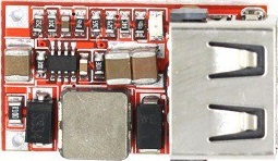
A USB regulator is an electronic component designed to maintain a stable output voltage for USB-powered devices. It is essential for ensuring that the voltage supplied through a USB port is within the safe operating range for connected devices, such as smartphones, tablets, and other peripherals. USB regulators are commonly used in applications where USB ports are used for charging or powering devices, including computer motherboards, portable battery packs, and standalone USB charging stations.
Explore Projects Built with usb regulator


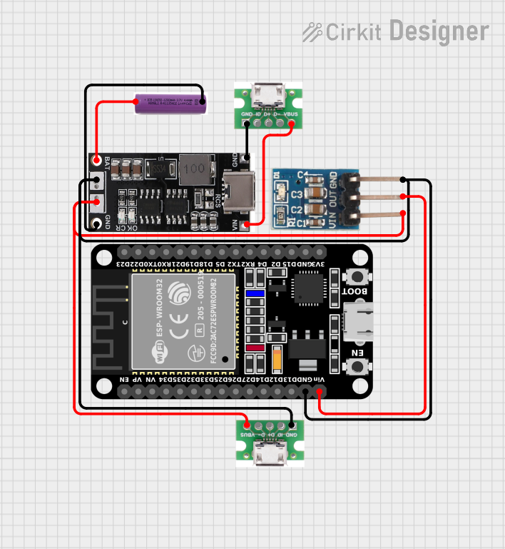
Explore Projects Built with usb regulator
Technical Specifications
Key Technical Details
- Input Voltage Range: Typically 4.5V to 5.5V (from USB port)
- Output Voltage: 5V (standard USB voltage)
- Output Current: Varies by model (e.g., 500mA, 1A, 2A)
- Efficiency: Depends on the design, can be >90% for switching regulators
- Operating Temperature Range: Usually -40°C to +85°C
Pin Configuration and Descriptions
| Pin Number | Name | Description |
|---|---|---|
| 1 | VIN | Input voltage from USB port |
| 2 | GND | Ground connection |
| 3 | VOUT | Regulated output voltage |
| 4 | EN | Enable pin (active high or low depending on model) |
| 5 | FB | Feedback pin (for adjustable output versions) |
Usage Instructions
How to Use the Component in a Circuit
- Connect the Input: Attach the VIN pin to the positive terminal of the USB power source and the GND pin to the ground terminal.
- Enable the Regulator: If the regulator has an enable pin (EN), connect it to a logic high level to turn on the regulator. For always-on applications, this pin can be tied directly to VIN.
- Connect the Output: The VOUT pin provides the regulated voltage. Connect this to the power input of your USB device.
- Feedback Connection: For adjustable versions, the FB pin may need to be connected through a voltage divider to set the desired output voltage.
Important Considerations and Best Practices
- Heat Dissipation: Ensure adequate heat sinking if the regulator is expected to handle high currents.
- Input Capacitance: Place a capacitor close to the VIN and GND pins to stabilize the input supply.
- Output Capacitance: Place a capacitor close to the VOUT and GND pins to stabilize the output voltage and reduce noise.
- Short Circuit Protection: Verify that the regulator has built-in short circuit protection or add an external fuse for safety.
Troubleshooting and FAQs
Common Issues
- Voltage Drop: If the output voltage is lower than expected, check for excessive load or insufficient input voltage.
- Overheating: If the regulator is too hot, reduce the load current, improve heat sinking, or check for short circuits.
- No Output: Ensure the EN pin is correctly driven and that there are no open circuits in the feedback loop (for adjustable versions).
Solutions and Tips
- Use a Multimeter: Verify input and output voltages with a multimeter to ensure they are within specifications.
- Check Connections: Revisit all connections, especially the ground, to ensure they are secure and free from corrosion or damage.
- Replace the Regulator: If troubleshooting steps fail, the regulator may be faulty and require replacement.
FAQs
Q: Can I use a USB regulator to charge my device faster? A: The charging speed depends on the current rating of the regulator and the device's charging capabilities. Ensure both are compatible for faster charging.
Q: Is it possible to adjust the output voltage of a USB regulator? A: Some USB regulators have an adjustable output. Consult the datasheet for the correct configuration of the feedback network.
Q: How can I ensure the longevity of my USB regulator? A: Avoid exceeding the recommended input voltage, output current, and thermal limits. Use proper heat sinking and input/output capacitors.
Example Arduino UNO Connection
// Example code for controlling a USB regulator with an Arduino UNO
// This code assumes the regulator has an enable pin

const int enablePin = 7; // Connect the EN pin of the regulator to digital pin 7

void setup() {
  pinMode(enablePin, OUTPUT); // Set the enable pin as an output
  digitalWrite(enablePin, HIGH); // Turn on the regulator
}

void loop() {
  // Your code to interact with the powered USB device goes here
  // ...
}
Note: This example assumes the USB regulator has an enable pin that is active high. Adjust the code accordingly if the enable pin is active low or if the regulator does not have an enable pin. Always consult the specific USB regulator datasheet for accurate connection and operation details.