How to Use LiPo Fuel Gauge (MAX1704X): Examples, Pinouts, and Specs
Introduction
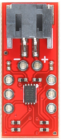
The LiPo Fuel Gauge (MAX1704X), manufactured by SparkFun (Part ID: TOL-20680), is a highly accurate battery fuel gauge designed specifically for lithium polymer (LiPo) batteries. It provides real-time voltage and state-of-charge (SOC) measurements, enabling efficient power management in portable devices. The MAX1704X uses advanced algorithms to estimate the remaining battery capacity without requiring a current-sense resistor or battery characterization.
Explore Projects Built with LiPo Fuel Gauge (MAX1704X)

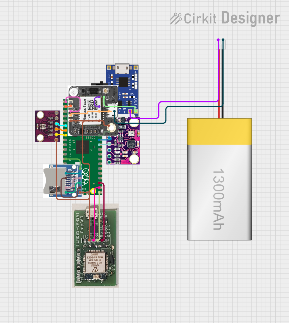


Explore Projects Built with LiPo Fuel Gauge (MAX1704X)
Common Applications and Use Cases
- Portable electronics (e.g., smartphones, tablets, and wearables)
- Battery-powered IoT devices
- Robotics and drones
- Power banks and backup power systems
- Any application requiring precise battery monitoring
Technical Specifications
The MAX1704X is a low-power, high-accuracy fuel gauge IC with the following key specifications:
| Parameter | Value |
|---|---|
| Operating Voltage Range | 2.5V to 4.5V |
| Battery Type Supported | Single-cell LiPo |
| State-of-Charge Accuracy | ±1% |
| Communication Interface | I²C (up to 400kHz) |
| Quiescent Current | 50µA (typical) |
| Operating Temperature Range | -40°C to +85°C |
| Package Type | 8-pin µMAX or 10-pin TDFN |
Pin Configuration and Descriptions
The MAX1704X has the following pinout:
8-Pin µMAX Package
| Pin Number | Pin Name | Description |
|---|---|---|
| 1 | VDD | Power supply input (2.5V to 4.5V) |
| 2 | SCL | I²C clock input |
| 3 | SDA | I²C data input/output |
| 4 | GND | Ground |
| 5 | THRM | Optional thermistor input for temperature monitoring |
| 6 | ALRT | Alert output for low SOC or other events |
| 7 | RST | Reset input (active low) |
| 8 | VSS | Ground (internally connected to GND) |
10-Pin TDFN Package
| Pin Number | Pin Name | Description |
|---|---|---|
| 1 | VDD | Power supply input (2.5V to 4.5V) |
| 2 | SCL | I²C clock input |
| 3 | SDA | I²C data input/output |
| 4 | GND | Ground |
| 5 | THRM | Optional thermistor input for temperature monitoring |
| 6 | ALRT | Alert output for low SOC or other events |
| 7 | RST | Reset input (active low) |
| 8 | VSS | Ground (internally connected to GND) |
| 9 | NC | No connection |
| 10 | NC | No connection |
Usage Instructions
How to Use the MAX1704X in a Circuit
- Power Supply: Connect the VDD pin to a 2.5V to 4.5V power source. Ensure the GND and VSS pins are connected to the circuit ground.
- I²C Communication: Connect the SCL and SDA pins to the corresponding I²C lines of your microcontroller. Use pull-up resistors (typically 4.7kΩ) on both lines.
- Battery Connection: Connect the LiPo battery's positive terminal to the VDD pin and the negative terminal to GND.
- Optional Thermistor: If temperature monitoring is required, connect a 10kΩ thermistor to the THRM pin.
- Alert Pin: The ALRT pin can be connected to a microcontroller GPIO pin to monitor low SOC or other alerts.
- Reset Pin: The RST pin can be used to reset the IC. Pull it low momentarily to reset.
Important Considerations and Best Practices
- Ensure the battery voltage is within the operating range (2.5V to 4.5V) to avoid damage to the IC.
- Use proper decoupling capacitors (e.g., 0.1µF and 1µF) near the VDD pin to stabilize the power supply.
- Keep the I²C lines as short as possible to minimize noise and ensure reliable communication.
- If using the ALRT pin, configure the microcontroller to handle interrupts for efficient monitoring.
- Avoid connecting multiple batteries in series or parallel directly to the MAX1704X, as it is designed for single-cell LiPo batteries.
Example Code for Arduino UNO
The following example demonstrates how to interface the MAX1704X with an Arduino UNO to read the battery voltage and SOC:
#include <Wire.h> // Include the Wire library for I²C communication

#define MAX1704X_ADDRESS 0x36 // Default I²C address of MAX1704X

void setup() {
  Wire.begin(); // Initialize I²C communication
  Serial.begin(9600); // Start serial communication for debugging

  // Optional: Reset the MAX1704X
  Wire.beginTransmission(MAX1704X_ADDRESS);
  Wire.write(0xFE); // Send reset command
  Wire.endTransmission();
}

void loop() {
  float voltage = readVoltage();
  float soc = readSOC();

  Serial.print("Voltage: ");
  Serial.print(voltage);
  Serial.println(" V");

  Serial.print("State of Charge: ");
  Serial.print(soc);
  Serial.println(" %");

  delay(1000); // Wait for 1 second before the next reading
}

float readVoltage() {
  Wire.beginTransmission(MAX1704X_ADDRESS);
  Wire.write(0x02); // Voltage register
  Wire.endTransmission(false);
  Wire.requestFrom(MAX1704X_ADDRESS, 2);

  uint16_t rawVoltage = (Wire.read() << 8) | Wire.read();
  return rawVoltage * 0.00125; // Convert to volts
}

float readSOC() {
  Wire.beginTransmission(MAX1704X_ADDRESS);
  Wire.write(0x04); // SOC register
  Wire.endTransmission(false);
  Wire.requestFrom(MAX1704X_ADDRESS, 2);

  uint16_t rawSOC = (Wire.read() << 8) | Wire.read();
  return rawSOC * 0.00390625; // Convert to percentage
}
Troubleshooting and FAQs
Common Issues and Solutions
No I²C Communication:
- Ensure the SCL and SDA lines are connected correctly and have pull-up resistors.
- Verify the MAX1704X's I²C address (default is 0x36) and update the code if necessary.
- Check for loose connections or damaged wires.
Incorrect Voltage or SOC Readings:
- Ensure the battery voltage is within the operating range (2.5V to 4.5V).
- Verify that the battery is properly connected to the VDD and GND pins.
- Check for noise or instability in the power supply.
ALRT Pin Not Triggering:
- Confirm that the alert thresholds are configured correctly in the MAX1704X registers.
- Ensure the microcontroller GPIO pin connected to ALRT is configured as an input.
FAQs
Q: Can the MAX1704X be used with batteries other than LiPo?
A: No, the MAX1704X is specifically designed for single-cell LiPo batteries and may not provide accurate readings for other battery chemistries.
Q: What is the typical accuracy of the SOC measurement?
A: The MAX1704X provides a state-of-charge accuracy of ±1% under typical conditions.
Q: Can I use the MAX1704X with a 2-cell LiPo battery?
A: No, the MAX1704X is designed for single-cell LiPo batteries only. For multi-cell configurations, consider using a different fuel gauge IC.
Q: How do I reset the MAX1704X?
A: You can reset the MAX1704X by pulling the RST pin low momentarily or by sending a reset command (0xFE) via I²C.