
How to Use Adafruit ADXL335: Examples, Pinouts, and Specs
 Design with Adafruit ADXL335 in Cirkit Designer
Introduction
The Adafruit ADXL335 (Part ID: 163) is a small, low-power, 3-axis accelerometer designed to measure acceleration in three dimensions (X, Y, and Z axes). It provides analog voltage outputs proportional to the acceleration experienced along each axis. This component is widely used in motion sensing applications, such as tilt sensing, vibration monitoring, and gesture recognition. Its compact size and low power consumption make it ideal for portable and battery-powered devices.
Explore Projects Built with Adafruit ADXL335
 Open Project in Cirkit Designer
 Open Project in Cirkit Designer
 Open Project in Cirkit Designer
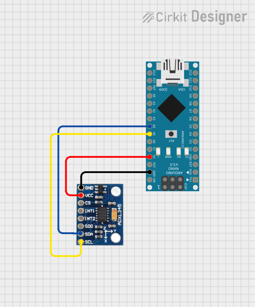 Open Project in Cirkit Designer
Explore Projects Built with Adafruit ADXL335
Open Project in Cirkit DesignerOpen Project in Cirkit DesignerOpen Project in Cirkit DesignerOpen Project in Cirkit DesignerCommon Applications
- Tilt and orientation detection
- Motion and vibration sensing
- Robotics and drone stabilization
- Gaming controllers and wearable devices
- Impact and collision detection
Technical Specifications
The ADXL335 is a versatile accelerometer with the following key technical details:
| Parameter | Value |
|---|---|
| Supply Voltage (Vcc) | 1.8V to 3.6V |
| Typical Operating Voltage | 3.3V |
| Current Consumption | 350 µA (typical) |
| Measurement Range | ±3g |
| Sensitivity | 300 mV/g (at 3.3V supply) |
| Bandwidth | Selectable via external capacitors |
| Output Type | Analog voltage |
| Operating Temperature Range | -40°C to +85°C |
| Dimensions | 20mm x 20mm x 1.45mm |
Pin Configuration and Descriptions
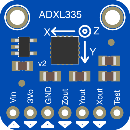
The ADXL335 breakout board from Adafruit has the following pinout:
| Pin | Name | Description |
|---|---|---|
| 1 | VCC | Power supply input (1.8V to 3.6V, typically 3.3V). |
| 2 | GND | Ground connection. |
| 3 | XOUT | Analog output voltage proportional to acceleration along the X-axis. |
| 4 | YOUT | Analog output voltage proportional to acceleration along the Y-axis. |
| 5 | ZOUT | Analog output voltage proportional to acceleration along the Z-axis. |
| 6 | ST | Self-test pin. Activates self-test mode when connected to VCC. (Optional use.) |
Usage Instructions
How to Use the ADXL335 in a Circuit
- Powering the Sensor: Connect the
VCCpin to a 3.3V power source and theGNDpin to ground. - Reading Outputs: The
XOUT,YOUT, andZOUTpins provide analog voltage outputs proportional to the acceleration along each axis. These outputs can be connected to an ADC (Analog-to-Digital Converter) for digital processing. - Filtering: Use external capacitors on the
XOUT,YOUT, andZOUTpins to set the bandwidth of the accelerometer. The recommended capacitor value is 0.1 µF for a bandwidth of approximately 50 Hz. - Self-Test: To verify the sensor's functionality, connect the
STpin toVCC. This will apply a known force to the sensor, and the outputs should change accordingly.
Important Considerations and Best Practices
- Power Supply: Ensure a stable power supply to avoid noise in the output signals.
- Analog Signal Handling: Use an ADC with sufficient resolution (e.g., 10-bit or higher) to accurately capture the sensor's output.
- Mounting: Securely mount the sensor to minimize mechanical vibrations that could affect readings.
- Bandwidth Selection: Adjust the external capacitors to set the desired bandwidth based on your application requirements.
- Calibration: Perform calibration to account for sensor offsets and improve accuracy.
Example: Connecting to an Arduino UNO
The ADXL335 can be easily interfaced with an Arduino UNO. Below is an example code to read and display the accelerometer's output:
// Define the analog input pins for the ADXL335
const int xPin = A0; // X-axis output connected to A0
const int yPin = A1; // Y-axis output connected to A1
const int zPin = A2; // Z-axis output connected to A2

void setup() {
  Serial.begin(9600); // Initialize serial communication at 9600 baud
}

void loop() {
  // Read the analog values from the ADXL335
  int xValue = analogRead(xPin); // Read X-axis value
  int yValue = analogRead(yPin); // Read Y-axis value
  int zValue = analogRead(zPin); // Read Z-axis value

  // Convert the analog values to voltage (assuming 5V reference)
  float xVoltage = xValue * (5.0 / 1023.0); // Convert X-axis reading to voltage
  float yVoltage = yValue * (5.0 / 1023.0); // Convert Y-axis reading to voltage
  float zVoltage = zValue * (5.0 / 1023.0); // Convert Z-axis reading to voltage

  // Print the results to the Serial Monitor
  Serial.print("X Voltage: ");
  Serial.print(xVoltage);
  Serial.print(" V, Y Voltage: ");
  Serial.print(yVoltage);
  Serial.print(" V, Z Voltage: ");
  Serial.print(zVoltage);
  Serial.println(" V");

  delay(500); // Wait for 500ms before the next reading
}
Notes:
- Ensure the Arduino's ADC reference voltage matches the ADXL335's output range.
- Use a 3.3V power supply for the ADXL335 to avoid damaging the sensor.
Troubleshooting and FAQs
Common Issues and Solutions
No Output or Incorrect Readings:
- Verify the power supply voltage is within the specified range (1.8V to 3.6V).
- Check all connections for loose wires or incorrect pin assignments.
- Ensure the ADC reference voltage matches the sensor's output range.
Noisy or Fluctuating Readings:
- Add decoupling capacitors (e.g., 0.1 µF) near the power supply pins to reduce noise.
- Use shielded cables or shorter wires to minimize electromagnetic interference.
Self-Test Not Working:
- Ensure the
STpin is properly connected toVCCduring the self-test. - Check the output voltages during self-test mode to confirm expected changes.
- Ensure the
Incorrect Acceleration Values:
- Perform calibration to account for sensor offsets and scale factors.
- Verify the orientation of the sensor and ensure it is mounted securely.
FAQs
Q: Can the ADXL335 measure static acceleration (e.g., gravity)?
A: Yes, the ADXL335 can measure both static acceleration (e.g., gravity) and dynamic acceleration (e.g., motion or vibration).
Q: What is the maximum bandwidth of the ADXL335?
A: The maximum bandwidth is 1600 Hz for the X and Y axes, and 550 Hz for the Z axis. However, the bandwidth is typically limited by external capacitors.
Q: Can I use the ADXL335 with a 5V microcontroller?
A: Yes, but you must use a voltage divider or level shifter to ensure the sensor's output voltages are compatible with the microcontroller's ADC input range.
Q: How do I calibrate the ADXL335?
A: Measure the sensor's output at known orientations (e.g., flat, tilted) and calculate offsets and scale factors to correct the readings.
This concludes the documentation for the Adafruit ADXL335.